
Introduction
One of the most important criteria to be considered in the purchase of an optical microscope is the required field of application. Another, perhaps equally important, is the state of (aberration) correction of the optical components, in particular, the objectives. Microscope objectives are perhaps the most important components of an optical microscope because they are responsible for primary image formation and play a central role in determining the quality of images that the microscope is capable of producing. Objectives are also instrumental in determining the magnification of a particular specimen and the resolution under which fine specimen detail can be observed and recorded using the microscope. The objective is the most difficult component of an optical microscope to design and manufacture, and is the first component that light encounters as it proceeds from the specimen to the image plane.
The optical components contained within modern microscopes are mounted on a stable, ergonomically designed base that allows rapid exchange, precision centering, and careful alignment between those assemblies that are optically interdependent. Together, the optical and mechanical components of the microscope, including the mounted specimen on a glass microslide and coverslip, form an optical train with a central axis that traverses the microscope base and stand. The microscope optical train typically consists of an illuminator (including the light source and collector lens), a substage condenser that serves to prepare illumination for imaging, specimen, objective, eyepiece, and detector, which is either some form of camera or the observer's eye.
Research-level microscopes also contain one of several light-conditioning devices that are often positioned between the illuminator and condenser, and a complementary detector or filtering device that is inserted between the objective and the eyepiece or camera. The conditioning device(s) and detector work together to modify image contrast as a function of spatial frequency, phase, polarization, absorption, fluorescence, off-axis illumination, and/or other properties of the specimen and illumination technique. Even without the addition of specific devices to condition illumination and filter image-forming waves, some degree of natural filtering occurs with even the most basic microscope configuration.
While some of the microscope optical components act as image-forming elements, others serve to produce various modifications to illumination of the specimen and also have filtering or transforming functions. Components involved in formation of images by the microscope optical train are the collector lens (positioned within or near the illuminator), condenser, objective, eyepiece (or ocular), and the refractive elements of the human eye or the camera lens. Although some of these components are not typically thought of as imaging components, their imaging properties are paramount in determining the final quality of the microscope image.
back to top ^Condensers
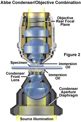
On upright microscopes, the condenser is located beneath the stage and serves to gather wavefronts from the microscope light source and concentrate them into a cone of light that illuminates the specimen with uniform intensity over the entire viewfield. Inverted (tissue culture style) microscopes mount the condenser above the stage and specimen on a frame pillar. It is critical that the condenser light cone be properly adjusted to optimize the intensity and angle of light entering the objective front lens. Each time the objective is changed, a corresponding adjustment must be performed on the condenser to provide the proper light cone to match the light cone (numerical aperture) of the new objective. A simple two-lens Abbe condenser is illustrated in Figure 2. In this figure, light from the microscope illumination source passes through the condenser aperture diaphragm, located at the base of the condenser, and is concentrated by internal lens elements, which then project light through the specimen in parallel bundles from every azimuth. The size and numerical aperture of the light cone is determined by adjustment of the aperture diaphragm. After passing through the specimen, the light diverges into an inverted cone with the proper angle to fill the front lens of the objective.
Aperture adjustment and proper focusing of the condenser (with regard to height in relation to the objective) are of critical importance in realizing the full potential of the objective. Specifically, appropriate use of the adjustable aperture iris diaphragm (incorporated into the condenser or just below it) is of significant importance in securing correct illumination, contrast, and depth of field. The opening size of this iris diaphragm controls the angles of illuminating wavefronts (and thus the aperture size) that bathe the specimen. Condenser height is controlled by a rack and pinion gear system that allows the condenser focus to be adjusted for proper illumination of the specimen. Correct positioning of the condenser with relation to the cone of illumination and focus (a step in establishing Köhler illumination) is critical to quantitative microscopy and to ensure the best digital images.
Condensers are divided primarily into classifications of imaging modality (such as brightfield, darkfield, and phase contrast), but also according to their degree of optical correction. There are four principle types of condensers with respect to correction of optical aberrations, as listed in Table 1. The simplest and least corrected (also the least expensive) condenser is the Abbe condenser that can have a numerical aperture up to 1.4 in the best models with three or more internal lens elements. Although the Abbe condenser is capable of passing bright light, it is not corrected for either chromatic or spherical optical aberrations. A typical Abbe condenser is illustrated in Figure 2. In its simplest form, the Abbe condenser has two optical lens elements that produce an image of the illuminated field diaphragm that is not sharp and is surrounded by blue and red color at the edges, characteristic of chromatic aberration.
The next level of condenser sophistication is split between the aplanatic and achromatic condensers that are corrected exclusively for either spherical (aplanatic) or chromatic (achromatic) optical aberrations. Achromatic condensers usually contain three to four lens elements and are corrected in two wavelengths (red and blue) for chromatic aberration. The achromatic condenser usually contains four lens elements and has a numerical aperture ranging from 0.9 to 1.4. This condenser design is useful for both routine and critical laboratory analysis with "dry" or oil immersion objectives and also for black and white or color photomicrography and digital imaging. The highest level of correction for optical aberration is incorporated in the aplanatic-achromatic condenser. This condenser is well corrected for both chromatic and spherical aberrations and is the condenser of choice for use in critical color imaging with white light. A typical aplanatic-achromatic condenser features eight internal lens elements cemented into two doublets and four single lenses.
Aberration Correction in Condenser Optical Systems
|
|||||||||||||||||
Table 1
Engravings found on the condenser housing include its type (achromatic, aplanatic, etc.), the numerical aperture, and a graded scale that indicates the approximate adjustment (size) of the aperture diaphragm. Condensers with numerical apertures above 0.95 perform best when a drop of oil is applied to their upper lens in contact with the undersurface of the specimen slide. This ensures that oblique light rays emanating from the condenser are not reflected from underneath the slide, but are directed into the specimen. In practice, this can become tedious and is not commonly done in routine microscopy, but is essential when working at high resolutions and for accurate imaging using high-power (and numerical aperture) objectives.
When the objective is changed, for example from a 10x to 20x, the aperture diaphragm of the condenser must also be adjusted to provide a new light cone that matches the numerical aperture of the new objective. This is done by turning the knurled knob or lever that controls the condenser aperture diaphragm. There is a small yellow or white dot, arrow, or index mark located on the condenser that indicates the relative size of the aperture when compared to the linear gradation on the condenser housing. Many manufacturers will synchronize this gradation to correspond to the approximate numerical aperture of the condenser. For example, if the microscopist has selected a 10x objective of numerical aperture 0.25, then the arrow would be placed next the value 0.18-0.20 (about 80 percent of the objective numerical aperture) on the gradation inscribed on the condenser housing.
back to top ^Eyepieces or Oculars
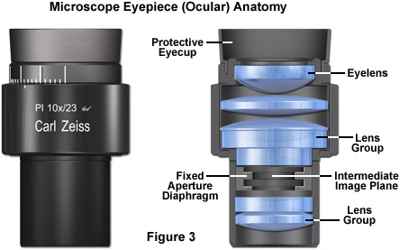
Eyepieces work in combination with microscope objectives to further magnify the intermediate image so that specimen details can be observed. Oculars is an alternative name for eyepieces that has been widely used in the literature. The best results in microscopy require that objectives be used in combination with eyepieces that are appropriate to the correction and type of objective. The basic anatomy of a typical modern eyepiece is illustrated in Figure 3. Inscriptions on the side of the eyepiece describe its particular characteristics and function. There are two major types of eyepieces that are grouped according to lens and diaphragm arrangement: the negative eyepieces with an internal diaphragm and positive eyepieces that have a diaphragm below the lenses of the eyepiece. Negative eyepieces have two lenses: the upper lens, which is closest to the observer's eye, is called the eye-lens and the lower lens (beneath the diaphragm) is often termed the field lens. In their simplest form, both lenses are plano-convex, with convex sides facing the specimen. Approximately mid-way between these lenses there is a fixed circular opening or internal diaphragm which, by its size, defines the circular field of view that is observed in looking into the microscope.
The simplest negative eyepiece design, often termed the Huygenian eye-piece, is found on most teaching and laboratory microscopes fitted with achromatic objectives. Although the Huygenian eye and field lenses are not well corrected, their aberrations tend to cancel each other. More highly corrected negative eyepieces have two or three lens elements cemented and combined together to make the eye lens. If an unknown eyepiece carries only the magnification inscribed on the housing, it is most likely a Huygenian eyepiece, best suited for use with achromatic objectives of 5x to 40x magnification. The other common eyepiece is the positive eyepiece with a diaphragm below its lenses, commonly known as the Ramsden eyepiece. This eyepiece has an eye lens and field lens that are also plano-convex, but the field lens is mounted with the curved surface facing towards the eye lens. The front focal plane of this eyepiece lies just below the field lens, at the level of the eyepiece diaphragm, making this eyepiece readily adaptable for mounting reticules.
Simple eyepieces such as the Huygenian and Ramsden and their achromatized counterparts will not correct for residual chromatic difference of magnification in the intermediate image, especially when used in combination with high magnification achromatic objectives as well as any fluorite or apochromatic objectives. To remedy this, manufacturers produce compensating eyepieces that introduce an equal, but opposite, chromatic error in the lens elements. Compensating eyepieces may be either of the positive or negative type, and must be used at all magnifications with fluorite, apochromatic and all variations of plan objectives (they can also be used to advantage with achromatic objectives of 40x and higher). In recent years, modern microscope objectives have their correction for chromatic difference of magnification either built into the objectives themselves or corrected in the tube lens.
Compensating eyepieces play a crucial role in helping to eliminate residual chromatic aberrations inherent in the design of highly corrected objectives on older finite tube length microscopes. Hence, it is preferable that the microscopist uses the compensating eyepieces designed by a particular manufacturer to accompany that manufacturer's higher-corrected objectives. Use of an incorrect eyepiece with an apochromatic objective designed for an older finite (160 or 170 millimeter) tube length application results in dramatically increased contrast with red fringes on the outer diameters and blue fringes on the inner diameters of specimen detail. Additional problems arise from a limited flatness of the viewfield in simple eyepieces, even those corrected with eye-lens doublets. More advanced eyepiece designs resulted in the Periplan eyepiece design (see Figure 3). This eyepiece contains seven lens elements that are cemented into a single doublet, a single triplet, and two individual lenses. Design improvements in periplan eyepieces lead to better correction for residual lateral chromatic aberration, increased flatness of field, and a general overall better performance when used with higher power objectives.
Modern microscopes feature vastly improved plan-corrected objectives in which the primary image has much less curvature of field than older objectives. In addition, most microscopes now feature much wider body tubes that have greatly increased the size of intermediate images. To address these new features, manufacturers now produce wide-eyefield eyepieces that increase the viewable area of the specimen by as much as 40 percent. Because the strategies of eyepiece-objective correction techniques vary from manufacturer to manufacturer, it is very important to use only eyepieces recommended by a specific manufacturer for use with their objectives. Additionally, most eyepieces on research-level microscopes have a focusing ring, which makes it possible to precisely focus on reticles that are mounted into the space where the intermediate image resides. The focusing ring also makes it possible to establish a condition on the microscope that is referred to as being parfocal, where operators with different eyesights can configure the microscope in such a manner that the images produced by the objective remain in focus when a new objective is inserted into the optical path.
back to top ^Objectives
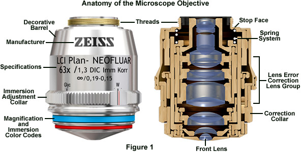
Microscope objectives are by far the most complex assemblies in the optical train. In contrast to the condenser and eyepieces, which contain between two and eight lenses, highly corrected objectives with numerical apertures above 1.0 can feature up to 15 or more lens elements and groups (see Figure 1). Objectives are fabricated with differing degrees of optical correction for both monochromatic (spherical, astigmatism, coma, distortion) and polychromatic aberrations, as well as field size and flatness, wavelength transmission band, birefringence, freedom from fluorescence and a variety of other factors that contribute to background noise. The two main criteria in objective manufacture are the elimination of chromatic errors and the flatness of the intermediate image that when perfectly corrected, provide an image with edge-to-edge sharpness, even with large fields of view. Depending upon the degree of correction, objectives are generally classified as achromats, fluorites, and apochromats, with a plan designation added to lenses with low curvature of field. Furthermore, objectives can be specifically classified into transmitted light and reflected light versions. The transmitted light versions popular in biological applications are usually designed for use with coverslips (in most cases, 170 micrometers in thickness). Reflected light (often termed Epi) objectives feature specially coated glass surfaces (antireflective coating) to avoid reflections in the optics when examining specimens lacking a coverslip. In fact, these objectives are specifically designed to be used on specimens without a coverslip.
Modern microscope objectives belong to a broad family known as infinity color corrected optics that produce a parallel bundle of wavefronts (leaving the rear focal plane), which are then focused onto the intermediate image plane using a tube lens. Because the light rays in these infinity optics are projected in parallel between the objective and the tube lens, filters, prisms, beamsplitters, reflectors, and other plane-parallel components can be inserted into the optical train without the need for additional optical components. Also, infinity corrected objectives are specifically matched in terms of optical factors to a tube lens to produce the final, fully-corrected intermediate image. Classical microscopes with finite optical systems require the eyepiece lenses to perform a portion of the aberration compensation work. The parfocal length of infinity-corrected optical systems (in effect, the distance from the objective mount to the specimen) is in most cases 45 millimeters so that individual objectives are optically and mechanically parfocalized in such a manner that the focal plane is maintained after an objective change without significant re-focusing.
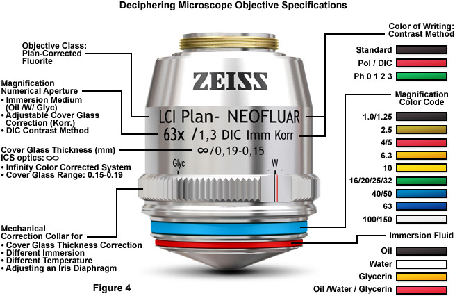
Most of the high-performance objectives feature spring mounts (see Figure 1) to protect the specimen, and many of the immersion objectives have nosepieces that can be snapped into the top position of their spring mount to enable the easy application of immersion fluids. The glass selected for objective fabrication must have suitable refractive index and dispersion, homogeneity, absence of strain, high chemical resistance, low thermal expansion, resistance to climatic changes, and high light transmission through the near-ultraviolet, visible, and near-infrared portions of the spectrum. In terms of how the various correction factors for objectives are categorized, the achromats have good color correction in two wavelengths, feature relatively flat fields in the center of the image, but require refocusing to observe details in the peripheral areas. Achromats are produced in versions designed for polarized light and phase contrast, but not fluorescence or differential interference contrast (DIC). Plan and epi-plan objectives are improved achromat versions with excellent flatness of field up to diameters of 24 millimeters or more. In addition, reflected light achromat objectives exhibit excellent contrast and a variety of working distances. The specifications required to identify objectives (see Figure 4) are usually inscribed on the decorative barrel protecting the internal lens elements.
The more highly corrected fluorite and plan-fluorite objectives have better color correction (at least three wavelengths) and feature flat fields (plan versions) in viewfields up to 26 millimeters in diameter. Due to the use of more advanced specialized glasses, fluorites are able to transmit ultraviolet wavelengths with high efficiency. Fluorite objectives are available for all contrast-enhancing modes, and special high-quality versions are available for polarized light and DIC. The apochromat objectives are the best performers and so are produced at the highest numerical aperture with color correction for at least four wavelengths. Plan versions reduce transmission efficiency, but produce spectacular images with a high degree of field flatness over the entire viewfield. As the need for specialized objectives grows with advances in technology, new apochromats are being designed to push the envelope with regards to color correction (360 to 700 nanometers or more), numerical aperture (up to 1.49), working distance, and suitability for various immersion media.
Achromats are the most widely used objectives and are commonly found on both teaching and research-level laboratory microscopes. They are satisfactory objectives for routine laboratory use, but because they are not corrected for all colors, a colorless specimen detail is likely to show, in white light, a pale green color at best focus (secondary axial color). Apochromatic objectives usually contain two lens doublets and a lens triplet for advanced correction of both chromatic and spherical aberrations. With apochromat and fluorite objectives, the diffraction-inducing spreading of the intensity distribution can be virtually eliminated. An achromat objective still has substantial intensity in the first fringe, while the apochromat approaches the theoretical resolution limit where the longitudinal chromatic aberration is greater than the wave-optical depth of field. Because apochromat objectives require lens elements having abnormal dispersion characteristics, their specifications may not be ideal for some specific applications, such as fluorescence excitation in the near ultraviolet, DIC, and other forms of microscopy utilizing polarized light. For this reason, a fluorite objective may be more suitable. Due to modern coating technologies in newly designed apochromats, remarkably sharp images with high contrast can be obtained even in those instances where the apochromat was inherently limited.
Conclusions
The first stage of the microscope optical train (and perhaps the most neglected) is the lamphouse, which contains the lamp and collector lens system. This unit is responsible for establishing the primary illumination conditions for the microscope. Light emitted by a tungsten-halogen or arc-discharge is passed through the collector lens system and the filament or arc is focused onto the front focal plane of the condenser (objective in reflected epi-fluorescence). The first image plane in the microscope optical train occurs at the position of the field diaphragm. Thus, the lamphouse coupled with the field diaphragm produces the necessary illumination pattern to sufficiently image specimens in a wide variety of imaging modes. In the optical microscope, conjugate planes are imaged into each other and can collectively be observed while examining a specimen in the eyepieces. The field iris diaphragm, adjacent to the lamp collector lens, is imaged sharply into the same plane as the specimen by the microscope condenser. Images of both the field diaphragm and the specimen are formed in the intermediate image plane by the objective and are projected into the fixed field diaphragm of the eyepiece, where the focusing reticle is located. Subsequently, the eyepiece (in conjunction with the observer's eye) forms images of all three previous image planes on the sensor surface of an imaging system or the retina of a human eye. The field diaphragm, specimen, intermediate image, and retina all constitute a set of conjugate image planes, spaced throughout the microscope optical train, which appear simultaneously in focus.
Contributing Authors
Rudi Rottenfusser - Zeiss Microscopy Consultant, 46 Landfall, Falmouth, Massachusetts, 02540.
Erin E. Wilson and Michael W. Davidson - National High Magnetic Field Laboratory, 1800 East Paul Dirac Dr., The Florida State University, Tallahassee, Florida, 32310.