
Introduction
Metal halide illumination sources are rapidly emerging as a serious challenger to the application of mercury and xenon arc lamps for investigations in fluorescence microscopy. These light sources feature a high-performance arc discharge lamp housed in an elliptical reflector that focuses the output into a liquid light guide for delivery to the microscope optical train. Advanced versions also contain internal filter wheels for wavelength selection, shutters, and neutral density filters to control intensity. The metal halide lamps that are most useful for microscopy have an emission output featuring pressure-broadened versions of the prominent mercury arc spectral lines in addition to higher radiation levels in the continuous regions between lines (see Figure 1). As a result, metal halide lamps generally produce much brighter images of fluorophores that have absorption bands falling in the spectral regions between mercury lines, including enhanced green fluorescent protein (EGFP), fluorescein, Cy2, and Alexa Fluor 488. Because the off-peak intensities in metal halide lamps are about 50 percent more powerful than mercury arc lamps, these sources are becoming a favorite for live-cell imaging experiments using EGFP. Furthermore, metal halide lamps produce a more uniform irradiance than mercury lamps (both spatially and temporally), a quality that renders these sources far more reliable for quantitative assays. Commercial metal halide light sources designed for microscopy have extended arc lamp life spans (up to 2000 hours versus 200 hours for mercury lamps) and eliminate traditional alignment problems to provide uniform illumination across the viewfield.
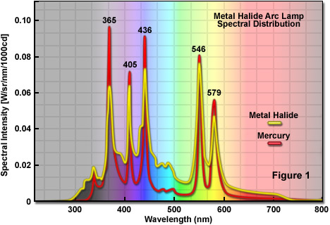
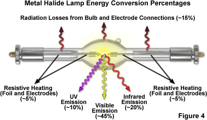
Similar to their mercury arc counterparts, metal halide lamps feature several prominent emission lines in the ultraviolet, violet, blue, green, and yellow spectral regions that are significantly brighter than the continuous averaged output (as illustrated in Figure 1). Almost 90 percent of the electrical energy supplied to metal halide lamps is efficiently converted into radiation. The remainder is primarily lost through resistive heating. Approximately 75 percent of the consumed power is radiated by the discharge arc, while around 15 percent is emitted by the electrodes and the hot envelope (see the breakout of metal halide energy conversion percentages in Figure 4). Of the light emitted by the arc, more than half (around 55 percent) resides in the ultraviolet and visible wavelengths between 350 and 700 nanometers. The spectral lines in metal halide lamps (arising from elemental excited state transitions in mercury vapor) occur at 365, 405, 436, 546, and 579 nanometers, enabling these light sources to be quite efficient when used to image fluorophores that were designed specifically for excitation by mercury arc lamps. These include DAPI (4',6-diamidino-2-phenylindole; 365 nm line), Alexa Fluor 405 (405 nm line), Cy3 and rhodamine (546 nm line), and MitoTracker Red (579 nm line). In addition, several of the more useful fluorescent proteins (Cerulean, tandem dimer Tomato, and Kusabira Orange) fall into this category. The higher radiation levels in off-peak regions, coupled with the superior temporal stability of metal halide lamps, renders these sources more useful than mercury arc lamps for imaging fluorophores excited in the 480 to 500 nanometer region. Metal halide lamps are also more suitable than mercury lamps for quantitative imaging of ratiometric dyes.
Optical Power of Metal Halide Lamps
|
||||||||||||||||||||||||||||||||||||||||||
1ZEISS Filters 2Semrock Filters
Table 1
Presented in Table 1 are the optical output power values of a typical (ZEISS HXP) 150-watt metal halide light source after passing through the microscope optical train and selected fluorescence filter sets. Power (in milliwatts/cm2) was measured at the focal plane of the microscope objective (40x fluorite dry, numerical aperture = 0.85) using a photodiode-based radiometer. Either a mirror with greater than 95% reflectivity from 350 to 800 nanometers or a standard fluorescence filter set was used to project light through the objective and into the radiometer sensor. The light throughput loss in a microscope illumination system can vary between aproximately 50 and 99 percent of the input power, depending upon light source coupling mechanism and the number of filters, mirrors, prisms, and lenses in the optical train. As an example, for a typical research-grade inverted microscope coupled to an external metal halide illumination source, less than 5 percent of the light exiting the liquid light guide at the entrance of the collimating lens system is available for excitation of fluorophores positioned at the objective focal plane. A similar range of light loss occurs with traditional xenon and mercury arc discharge lamps secured directly to the illuminator through a lamphouse.
Unlike xenon and mercury arc lamps, the metal halide lamps used in microscopy are equipped with elliptical reflectors into which the bulb is embedded at the factory during manufacture. The lamps are designed to generate a concentrated spot of light at a specified distance in front of the reflector (the lamp focal length; see Figure 2). One of the fundamental advantages of pre-assembled reflector lamps (which are manufactured to very close tolerances) is that each time the lamp is replaced, the reflector is also replaced into a fixed position within the lamphouse, thus eliminating the stringent and cumbersome alignment requirements of mercury and xenon arc lamps. The reflectors on metal halide lamps are coated with multiple dichromatic interference filter layers that enable much of the thermal (infrared) radiation to pass through the reflector while the ultraviolet and visible wavelengths are concentrated at the focused spot. A typical metal halide lamp configuration for microscopy is presented in Figure 2. The launch into a liquid light guide is controlled by a hollow aluminum cone (or similar collector) interfaced to a lamp holder that serves to position the lamp in exact proximity to the guide's input aperture. This design ensures that an even distribution of luminous intensity and color temperature from the illumination spot is directed into the light guide.
The luminous flux is a quantity that corresponds to the light emitted by a metal halide lamp in all directions and depends directly on the input power. That portion of the luminous flux that is available for specimen illumination is governed to a large extent by the optical system being employed, but typically only about 60 percent is available even with the highest quality components. The system efficiency (the usable system luminous flux; see Figure 2), which is an indicator of the amount of light actually available to the microscope, is even lower. In the case of metal halide lamps housed in elliptical reflectors, the luminous flux efficacy is a senseless quantity because light is only emitted in a single direction. Rather, the usable luminous flux that is directed to the illumination spot at the entrance to a light guide is a more precise definition of the light available for transport to the microscope optical system. It should be noted that additional optical components installed into the system, such as thermal protection filters and focusing condenser lenses, reduce the luminous flux entering the light guide. Thus, a more useful term for describing the illumination power of metal halide lamps is the system luminous flux, which is defined as the amount of light actually emerging from the external lamphouse and available to the microscope.
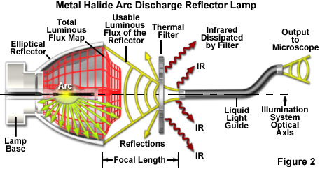
Illustrated in Figure 2 is a schematic ray-trace diagram of a typical metal halide arc lamp housed in an elliptical reflector of the type commonly employed in fluorescence microscopy. A large proportion of the total luminous flux emitted by the lamp is efficiently gathered by the collection reflector (denoted as a red wireframe in Figure 2) and focused at the entrance plane of the liquid light guide. The light focused by the collection mirror is referred to as the useable luminous flux of the reflector, and most of this light passes through a thermal (infrared) filter to remove as much heat as possible. A small percentage of the useful visible wavelengths are reflected from the surface of the filter and possibly from other components in the lamphouse. As a result, some of the useable luminous flux from the reflector is lost. Light that successfully enters the liquid light guide is scrambled to remove spatial and temporal inhomogeneities, and then passed on to a beam expander at the input port of the microscope. This light is often referred to as the useable system luminous flux, as described above.
In short-arc metal halide lamps, a pronounced area of maximum luminance (termed a hot spot) occurs very near the ends of each electrode and decreases progressively toward the center of the arc. As a result, the highest illuminance values are found in those lamps having the shortest electrode gaps (assuming a fixed lamp power). In a vertical operating position, the luminance distribution in the arc is rotationally symmetrical, but due to the inhomogeneous thermal distribution within the arc, there is a point of maximum luminance a short distance in front of the upper electrode. In the horizontal operating position (as is the orientation for most metal halide lamps used in microscopy), the two points of maximum luminance are approximately the same. However, the overall arc geometry is deflected upwards slightly in horizontal lamps due to convection currents in the surrounding fill gas. Thus, the optical system should be designed to take advantage of the area of maximum luminance nearest the electrodes. In metal halide lamps housed in an elliptical reflector, this area is positioned at the internal focal point near the base of the reflector (see Figure 2). The exact location of the lamp within the reflector is determined by measuring the average luminance along the lamp axis and over the entire length of the arc.
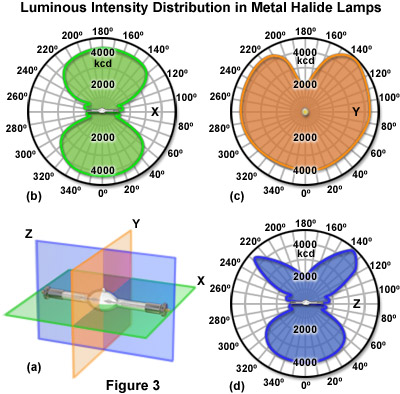
The design of optical systems for optimum performance with reflector-based metal halide lamps must take into account the luminous intensity distribution surrounding the lamp. This quantity is defined as the directional luminous flux and represents the combined measurement of the individual luminous intensity values in various directions, which must be gathered at the focal point of the reflector and projected into an illumination spot for transfer to the microscope optical system. The spatial luminous intensity distribution of a metal halide lamp varies widely with lamp design (in effect, single-ended or double-ended) and the operating position. The most convenient method to examine these distributions is to plot intensity on a polar diagram for a specific plane surrounding the lamp (see Figure 3). Polar intensity distribution maps are often referred to as indicatrices. Presented in Figure 3 are polar intensity distribution maps plotted in all three dimensions (x, y, z) for a typical double-ended metal halide lamp. Note the symmetrical distribution that occurs around the lamp in the horizontal (x) plane. In contrast, the tip-off stem blemish positioned at the top of the lamp induces perturbations in the intensity maps (near 180°) for the other two axes. Because of the significant intensity loss in regions surrounding the blemish, reflector system designs must be able to compensate in order provide an even field of illumination. Several of the newer lamp designs (known as tip-less) eliminate the blemish to produce more uniform intensity distributions.
Reflector metal halide lamps targeted for microscopy are usually equipped with elliptically-shaped focusing mirrors, but other versions feature reflectors that form parallel light bundles. Elliptical reflectors feature a luminous intensity characteristic that varies significantly as a function of distance from the front focal plane, but many of these collectors can gather up to 85 percent of the total emitted light. Unfortunately, however, the projected ray bundle can be disrupted by a dark central spot where the wavefronts are obscured by the end of the plasma tube (see the polar maps in Figure 3). Focal lengths for high-performance elliptically shaped collector lamps range from approximately 24 to 45 millimeters (measured from the front edge of the reflector). Parabolic and spherical reflectors produce parallel wavefronts that enable the source to be imaged into infinity, and therefore, are not generally useful in external lamphouses that transfer illumination to the microscope through fiber optic cables or liquid light guides. A critical element on reflector lamps is to examine the overall design criteria to ensure that only a minimal amount of radiation (in fact, the least amount possible) is reflected back toward the lamp itself. Improper back-illumination produces excessive quantities of heat in the regions surrounding the tube and stems, a potentially serious artifact that can be significantly detrimental to the physical integrity, performance, and cooling strategy for the lamp.
Optically perfect metal halide ellipsoidal reflector lamps project a wavefront field that segregates the different areas of the arc into a rainbow of color temperatures, ranging from bluish white (having a color temperature of approximately 6500 K) in the central focal region to more reddish hues at the periphery (4500 to 5000 K). For microscopy applications, however, a mixture of these different wavelength components is desired in order to form a homogeneous and uniform color balance that can be further refined with the aid of selected interference filters for optimum fluorophore excitation. In practice, the solution is to carefully design elliptical reflectors to contain three rotational permutations having different radiuses of curvature to achieve the best possible blend of different color components from the arc at the input plane of the liquid light guide. The longest wavelengths of undesirable infrared light are largely removed by filtration (see Figure 2), but some of the other more useful wavelengths are also reflected by the optical and mechanical components in the lamphouse. In general, metal halide lamps designed for microscopy have a color temperature balance approaching 6000 K, similar to that featured by xenon arc lamps but with approximately twice the luminous efficacy.
Metal Halide Lamp Operation
Metal halide lamps are started by the brief application of a high voltage trigger (in the range of 5 to 30 kilovolts) to the electrodes using a specialized ignition circuit. The voltage pulse ionizes the argon fill gas (sometimes referred to as the starter gas) and initiates the burn sequence, which subsequently produces vaporization and ionization of the elemental mercury and metal halide components as the lamp temperature and pressure begins to rise. Metal halide lamps don't achieve their full color spectrum and emission stability characteristics until they reach their designated operating temperature, a time period that can range up to five minutes. Once the lamp is fully operational, vaporized metal halide salts are dissociated by the arc and excited into higher energy states from which they emit spectral lines. As they diffuse closer to the cooler envelope inner walls, the rare earth metals recombine with halogen to repeat the excitation cycle. The choice of rare earth metals added to the envelope fill influences the emission spectral properties of the lamp (color rendering index), as well as contributing to the luminous efficacy. Metal halide salts exhibit lower vapor pressures than the elemental mercury added to the bulb, which also serves as a buffering gas to determine the operating voltage of the lamp. Thus, mercury controls the current-voltage lamp characteristics, while the metal halide salts contribute primarily to the quantity of light output and the spectral content after lamp warm-up. Iodide salts are commonly used in metal halide lamps because they are less stable (dissociate more readily) than chlorides and bromides. In many cases, thallium iodide is added to metal halide lamps to adjust the output color temperature. The spectral output and energy conversion efficiency, as well as the overall performance of a metal halide lamp (summarized in Figure 4), can also be affected by fluctuations in the power supply as well as manufacturing variations.
The operating temperature of a metal halide lamp is critical to optimum lamp performance, with drastic fluctuations often leading to undesirable emission characteristics or, at worst, premature envelope or seal failure. In general, bulb temperatures fall into a window between 800 and 1000°C during normal operation. Exceeding these temperatures leads to devitrification of the quartz envelope, which usually decreases light output and increases the chances for rupture. At lower temperatures, decreased vaporization of mercury and metal halide salts results in a change of electrical characteristics that shifts the spectral distribution, reduces luminous flux output, and produces blackening of the envelope walls. The temperature of the lamp seals should also be maintained within the manufacturer's recommended range. At high temperatures, the possibility of accelerated oxidation endangers seal integrity, which can lead to failure due to a stress fracture between the metal and the quartz stem. In metal halide lamps with a direct current power supply, the anode seal operates at a considerably higher temperature than the cathode and must be supplied with a heat sink or fan in most lamphouse configurations.
The orientation of a metal halide lamp during operation can have a major influence on performance and the manufacturer's recommendations should always be followed. In most cases the preferred orientation places the long axis of the discharge tube horizontally, regardless of lamp design parameters. The horizontal orientation enables metal halide lamps to exhibit almost symmetrical thermodynamic characteristics in which a uniform change in temperature occurs from the two hot spots near the electrodes down to the ends of the shafts. In a vertical position, the electrodes often acquire an uneven temperature balance that compromises lamp performance. Another important aspect of lamp orientation is the position of the pumping stem tip-off (PST) envelope blemish. This is the region where the fill gas tube was sealed during lamp fabrication. The tip-off blemish results in a distortion of bulb geometry and can be detected as a cold spot (in relation to the rest of the envelope) in thermal imaging maps of lamps during operation. Metal halide lamps mounted in the horizontal configuration should have the PST facing upwards (at the top of the bulb), and this is done at the factory for lamps integrated into reflectors. Such positioning prevents condensation of fill components in the PST region.
Metal halide lamps often require cooling to ensure proper operation. One of the most critical regions are the stem seals where molybdenum foils are embedded into the quartz and are susceptible to oxidation by atmospheric components at excessive temperatures. In most cases, the maximum permissible temperature at the outer shaft ends is 350° C, which can easily be maintained with simple cooling scenarios. Forced cooling using a brushless direct current fan is the method of choice for aftermarket manufacturers of light sources for microscopy. In addition to the stems, the reflector temperature is an important design factor in metal halide lamps. The temperature of the reflector surface should not exceed 250° C to prevent layers of the dichroic thin film from peeling. Cooling of reflectors requires a bit more attention in order to minimize the temperature gradient created along the surface of the reflector. Large temperature gradients can induce stress in the lamp and produce cracks in the reflector. Regardless of the cooling strategy for individual lamp components, it should be noted that cool air should never be blown directly on the discharge tube. The level of success in maintaining metal halide lamps at the proper operating temperature has a definite beneficial effect on lamp life, especially in terms of preventing devitrification and maintaining useful levels of luminous flux.
After a metal halide discharge lamp has been started, it should be allowed to warm completely to the recommended operating parameters (temperature and pressure) before it is turned off. In many cases the lamps are fully operational after a minute or two, but this value depends upon lamp design and specifications. After ignition, the lamp filler components (mercury, halides, and rare earth elements) vaporize in successive stages, while the lamp voltage, electrical output, and luminous flux gradually increase until they reach steady-state operating conditions. Rare earth elements are the last of the fill gases to evaporate so that metal halide lamps generate a blue-shifted spectral distribution until warm-up is completed. Shutdown is the reverse of startup with the rare earth elements being the first to condense. Premature termination of lamp operation can lead to rapid deterioration of the electrodes and blackening of the inner envelope walls, thus compromising future lamp performance. In effect, if a lamp is accidentally switched off too quickly during the startup phase, the filler components (mercury and rare earth halides) are often deposited on the internal walls of the envelope and on the electrodes. This artifact can be visualized as a dark opaque coating and can adversely affect re-ignition (in rare cases, permanently). In addition, the number of lamp startups has a significant impact on the life span, with more frequent ignitions leading to shorter lifetimes regardless of whether the lamp has been allowed to reach its proper operating temperature on each run before powering down.
Metal halide lamps are prone to similar instability artifacts that plague other arc discharge light sources (primarily mercury and xenon). The terms used to describe arc instability are numerous and include words such as flicker, jitter, wobble, and flutter that all refer to a fluctuation in brightness. Unlike traditional arc lamps, some varieties of metal halide lamps are operated with a choke circuit that results in frequencies in the range of 50 to 60 hertz being passed directly to the lamp. Therefore, the lamp will quench and re-ignite between a 100 and 120 times a second, which may interfere with high-speed digital cameras capturing extremely rapid frame rates, but is generally too fast to affect most microscope detectors. Newer electronic lamp circuits using direct current power supplies alleviate this phenomenon and also provide much better general stability characteristics. However, due to the inherent brightness fluctuations present in all arc lamp designs, the metal halide varieties exhibit short term instability in terms of electrode wear and internal lamp convection currents.
Electrodes in metal arc lamps slowly degenerate over time as the tips acquire deformities and an increasing larger radius that results in a reduction of current flow near the cathode tip and also increases the power level required to sustain the arc. The three most common artifacts associated with electrode wear are termed wander, flare, and flutter (see Figure 5). Arc wander occurs when the attachment point of the arc on the cathode tip travels to a new location, often following a circular pattern around the circumference of the electrode. Wander is accompanied by arc flare, which refers to a momentary change in brightness as the arc relocates to a new region on the electrode with a higher emissive character than the previous attachment point. Flutter occurs when convection currents in the fill gas generated by the temperature differential between the arc and envelope invoke a rapid lateral displacement of the arc column. Collectively, these sources of instability contribute significantly to poor lamp performance, but advances in power supply design for metal halide lamps are beginning to produce new systems that exhibit much better temporal and spatial stability over both short and long timeframes.

The ageing process of quartz envelopes in metal halide lamps is commonly known as devitrification (or recrystallization) and is manifested as the appearance of a milky-white coating on the inner walls of the discharge tube that is actually a physical change in the quartz structure itself. The extremely high operating temperatures and pressures to which the discharge tube is exposed over its lifetime slowly produce a regressive re-ordering of the amorphous quartz to a semi-crystalline state in some regions of the envelope. The white coating consists of silicon oxides that are accompanied by a loss of density and strength. When arc lamps reach the end of their life spans, much of the discharge tube has been completely devitrified and is at increased risk of bursting. In addition to the obvious safety hazards, devitrified discharge tubes also exhibit compromised photometric properties and should be replaced with new lamps.
Metal Halide Arc Lamp Construction
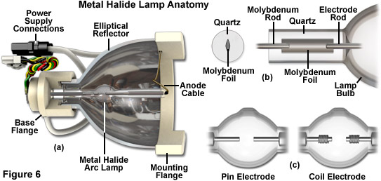
A wide variety of design motifs are employed in the construction of metal halide lamps, but those used in fluorescence microscopy are restricted to custom short-arc versions housed in elliptical reflectors. The discharge tube is fabricated from fused silica or quartz, which encloses the electrode system and contains the fill gases and metal salts. The discharge arc burns in the area between the tips of the cathode and anode (referred to as the electrode gap). Fused quartz is one of the few materials capable of withstanding the extreme mechanical stresses and thermal loads imposed on metal halide lamps, which must be able to endure long-term operation at temperatures approaching 950° C and pressures up to 40 atmospheres. In some high-performance lamp designs, the quartz envelope can range up to 5 millimeters in thickness. During manufacture, the electrodes are hermetically sealed within the lamp shafts and electrically bridged to the bases with molybdenum foil and pins (see Figure 6(b)). The lamp bases provide the connection to an external power supply and are also used for mechanical support. In lamps coupled to dichroic reflectors, the long axis of the quartz shaft is oriented parallel to the optical axis of the elliptical reflector (Figures 2 and 6(a)) so that the electrode gap can be aligned precisely at the focal point. One end of the lamp shaft is cemented into the ceramic reflector base while the other end projects into the center of the reflector and is electrically connected to the power supply with a cable.
The electrodes in metal halide lamps are fabricated with doped tungsten alloys and are identically shaped for versions intended to be used with alternating current (AC). Those lamps designed for direct current (DC) operation contain a more massive anode and a smaller, pointed cathode (similar to the electrodes in xenon arc lamps). In general, the electrodes used in metal halide lamps are divided into two categories, termed pin and coil electrodes (see Figure 6(c)). Coil electrodes are thinner versions of pin electrodes, but have a thin tungsten wire wound in either single or double layers around the tips. Electrode design has a profound influence on the temperature profile of the tungsten rod, ranging from the tip to the region that is embedded into the quartz shaft. In metal halide lamps, the electrode configuration must be compatible with the shape of the cup (the transition region between the bulb and the shaft), as well as the fill chemicals and the internal volume of the envelope bulb. Electrode design must also take into account the elimination of potential heat nests (regions at a higher temperature than their surroundings) and must offer the arc a stable foundation where optimum electron emission activity can take place. The best electrodes are sufficiently stable to enable the lamp to operate reliably throughout its life span.
Metal halide lamp shafts provide the mechanical and electrical connections between the bulb and the lamp base. Most of the lamps used in microscopy are isolated from the outside environment using a technique known as pinch sealing, which involves compressing the heated, malleable quartz shaft between two metal jaws. Compared with other metals, tungsten has a relatively low thermal expansion coefficient, but it is still approximately ten times larger than that of quartz. As a result, a tungsten electrode cannot be directly sealed to the quartz shaft without shattering the lamp due to thermal expansion during routine operation. The solution to this problem is handled by directing power into the quartz shafts with the aid of molybdenum ribbon (or foil), which has sharply etched edges that can dig into the quartz without causing it to break during heating. The thin molybdenum foil (approximately 20 micrometers by 2-4 millimeters in size) is welded to lead wires for connection to the power supply on one end, and to the tungsten electrode on the other end. These foils, depending on thickness, are capable of conducting upwards of 100 amperes of current during operation. In high power lamps, several layers of foil are often necessary to handle the high current loads.
The quality of light emitted by a metal halide lamp is primarily determined by the fill components. Depending upon the application, metal halide lamps can be filled with any number of up to 10 different components that perform critical functions, dictated by their chemical and physical properties, in the light generation process. One of the components present in all metal halide lamps is an inert starter gas, usually argon or xenon, which does not react with other fill components and exhibits desirable ignition properties. The lamps used in microscopy also contain liquid mercury vapor and halogens. Mercury concentration primarily affects the lamp operating pressure and governs the voltage requirements, as discussed above. The halogens most widely used in metal halide lamps are iodine and bromine, which react with the trace levels of rare earth metals to form halide salts. These salts exhibit a higher vapor pressure than the metals alone, enabling engineers to fine-tune the particle density of rare earths in the arc for adjustments of color temperature and other emission properties.
In most cases, metal halide lamp envelopes are filled with a surplus of halogen gas to host the halogen regenerative cycle, which serves to prevent evaporated tungsten from the electrodes being deposited on the inner walls of the envelope. The rare earth metals used in metal halide lamps belong to the lanthanide series and are usually dysprosium (Dy), thulium (Tm), and/or holmium (Ho). Varying the combination and concentration of these metallic elements can be used to modulate the emission spectral distribution in order to match the target application for the lamp. In general, the rare earths are chosen to provide a continuous daylight spectral output with high luminous efficacy. At room temperature, metal halide lamps exist at or below ambient pressure, but during operation the internal pressure can range between 10 and 40 atmospheres, depending upon the fill components.
The lamp base is a critical component that serves the dual purpose of providing mechanical support as well as an electrical connection to the power supply. On double-ended lamps, the base consists of metal sleeves (often termed ferrules) cemented to the ends of the lamp shafts. In some cases the sleeves are tapered cylinders that may be equipped with a thread or cable. The metal halide lamps designed for fluorescence microscopy applications requiring a liquid light guide (see Figures 2 and 6) essentially perform as single-ended lamps with a ceramic base coupled to an elliptical reflector. Depending on the lamp design, either the cathode or anode end of the lamp tube can be attached to the base, while the other end is bridged to an electrical connection in the reflector housing with a thin metal cable welded to the protruding molybdenum pin. Lamp bases participate in removal of heat from the unit during operation via a metallic contact surface (usually the sleeve). The base temperature at the contact point between the sleeve and the lampholder should not exceed approximately 350° C during operation, requiring aftermarket manufacturers to include heat sinks, large contact areas, fans, or other compensating features in their instrument designs.
The production of metal halide lamps for microscopy applications, which feature highly refined optical systems, requires tight geometrical tolerances for the lamps. In reflector lamps, the exact positioning of the bulb is critical because deviations of just a few millimeters can lead to a significant compromise in the uniformity of illumination. Microscopy is a demanding application in which the light emanating from the reflector must be very accurately focused in order to maximize the input to the liquid light guide. For this reason, the reflector metal halide lamps used in fluorescence microscopy are stringently aligned within the elliptical reflector during fabrication. Furthermore, lamp envelope and stem tolerances, which naturally feature wide variation similar to other molten glass products, must be carefully monitored to ensure the precise location of the arc gap with respect to the rear focal point of the reflector. Close tolerances are also essential to compensate for slight deviations of the electrodes from the lamp axis. Collectively, the numerous requirements for accurate lamp fabrication fall well within the capabilities of modern lamp manufacturing processes so that the current lineup of commercial metal halide lamps often meets and even exceeds the requirements of fluorescence microscopy.
As a final note, the nomenclature surrounding lamp identification varies widely by manufacturer with no universal standard yet in place. The metal halide lamps used in microscopy are grouped in the HTI family by Osram, where H is an abbreviation of the symbol for mercury (Hg or Hydragyrum), T refers to the German term for daylight (Tageslicht), and I indicates the presence of halogen compounds (iodides and bromides). Other designations in use by Osram are M or R for rare earth metals, S for safe lamps that have an external bulb surrounding the envelope, P for projection lamps, and C for cable-equipped. Ushio metal halide lamps are marketed under the tradename of EmArc® with a code prefix of SMH, the acronym for short-arc metal halide. Other manufacturers have similarly confusing nomenclature, so their product catalogs should be carefully reviewed in order to ensure the correct lamp choice for a particular application.
Lamphouses and Power Supplies
The power supply requirements for metal halide lamps differ somewhat for those of mercury and xenon arc lamps. Both alternating and direct current (AC and DC) power supplies can be used with metal halide lamps (depending upon the lamp design parameters), but both types must incorporate similar features, including ignition and ballast circuits, power stabilization, and the proper current profile during the lamp startup phase. Metal halide power supplies require cooling, usually accomplished with fans and heat sinks. Because all arc lamps generally require high voltages to initiate burning, their power supplies usually involve two stages, a main supply circuit and an igniter module. During the start phase, the main power supply typically outputs a voltage ranging between 200 and 350 volts to the igniter, which boosts the output to a level between 5 and 30 kilovolts for ignition, depending on the lamp's hot-restrike capabilities. Once the lamp has started, the voltage can be dropped to an operational range of 20 to 100 volts. Among the mandatory requirements for metal halide power supplies is that all electrical connections should be well isolated from each other as well as ground potential to avoid arcing.
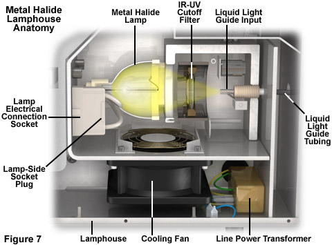
Illustrated in Figure 7 is a cutaway view of the internal components in a typical aftermarket metal halide lamphouse designed with a liquid light guide coupler for applications in fluorescence microscopy. Virtually all modern external lamphouses use light guides (either optical fibers or liquid) to mount the hot lamp at a safe distance from the sensitive microscope components, thus reducing heat transfer and ensuring a greater level of thermal stability for long term experiments. The metal halide lamp and reflector unit is mounted using clips to precisely locate the focal spot at the input aperture of the light guide. In some lamphouses, an ultraviolet and infrared blocking filter is positioned between the lamp and the input to the light guide (see Figures 7 and 8). Installing the liquid light guide is accomplished by inserting the input connector into the front or rear mount on the lamphouse until it is firmly seated (termed a snap-in and quick release coupler). The other end of the light guide is coupled to a specialized expansion lens system that is specific for each microscope design. Metal halide lamphouses feature both alternating and direct current power supplies with internally mounted igniters and ballasts, and usually incorporate a small electric fan beneath the lamp base to provide forced air cooling. Because lamps are aligned with their reflectors to very close tolerances at the factory, changeover is simply a matter of removing a spent lamp and inserting the replacement.
To avoid possible heat damage to the light scrambler (and microscope), infrared radiation as well as other potentially damaging emission wavelengths generated by the lamp should be removed before they enter the fiber or light guide, and this is most conveniently done using the appropriate filters. In the ideal case, only wavelengths critical to image formation and fluorophore excitation should leave the light source and be sent to the microscope optical train (optical fiber and liquid light guide transmission profiles are presented in Figure 8). Rather than relying on broadband mirrors, cold mirrors and customized bandpass interference filters can be employed to allow unwanted heat to escape and to select the light wavelengths transmitted to the light guide input aperture. The wavelength band normally desired for general purpose microscopy applications ranges from approximately 360 to 700 nanometers. Unneeded wavelengths that can damage living cells or the microscope, including those in the near-infrared and ultraviolet, can be allowed to pass through dichromatic mirrors (an infrared transmitter is denoted a cold mirror and an ultraviolet transmitter a hot mirror) and be absorbed in the lamp housing. As a further added benefit, the dissipation of heat by a cold mirror reduces light source movement caused by thermal expansion of the mechanical and optical components to ensure that the highest possible level of radiant flux is transmitted to the specimen.
The more advanced aftermarket and OEM (original equipment manufacturer) lamphouses contain a number of features that are very convenient for live-cell imaging in fluorescence microscopy. Among these added conveniences are light shutters, filter wheels, lamp life indicators, output intensity control, and customized interfaces that are easily integrated into microscope control software. Most metal halide lamphouses contain at least an adjustable iris that enables control over lamp intensity and some models incorporate variable neutral density filters for more precise adjustment. Electronic monitoring of lamp elapsed runtime and temperature is another useful feature incorporated into many metal halide lamphouses. Those systems that continually monitor lamp temperature are useful for preventing inadvertent hot-restrikes until the lamp cools to a safe state. Integral filter wheels are becoming more common in metal halide lamphouses. These units allow the operator to conveniently insert a choice of excitation filters directly into the remote lamphouse, thus eliminating the potential vibration artifacts that accompany a filter wheel attached directly to the microscope. Light shutters, which are quite useful to control the illumination period during live-cell imaging, can be controlled manually or through software. Most metal halide lamphouses can be connected to the host computer by a universal serial bus (USB) or RS-232 serial port. Convenient software plug-ins offered by the aftermarket lamphouse manufacturers can be nested into the more popular microscope control software packages.
Liquid Light Guides
The preferred optical illumination scheme in fluorescence microscopy is Köhler illumination, which serves to uniformly illuminate the image field using a spatially complex light source by imaging only a portion of the source at the focal plane of the condenser (or the objective rear focal plane in epi-illumination). Light striking the specimen is evenly distributed, although this light may not arrive from all possible azimuths with equal intensity. Another critical feature of Köhler illumination is control of the coherence of light from the source, but it is also possible to achieve homogeneous illumination using a light guide. The application of liquid light guides to microscopy applications enables scrambling or mixing of light to decrease spatial and temporal coherence. In metal halide lamphouses, light emanating from the reflector is focused onto the input aperture of a single-mode optical fiber or a liquid light guide (see Figures 2 and 7). Thermal motion in the liquid light guide constantly alters the optical path and scatters light so that both spatial and temporal coherence are effectively eliminated
Although less frequently employed in modern metal halide lamphouses, coiled single-mode optical fibers produce reflections from the cladding that constantly change as the fiber flexes slightly, generating an exit beam that is effectively uniform in intensity over time and space. The technique of vibrating the fiber at frequencies up to 100 kilohertz has been reported to be effective in light scrambling as well, but requires additional equipment. The phase of light emerging from an optical fiber is scrambled due to the varying pathlengths of light waves passing through the fiber, although the high radiance and chromatic character are preserved. The exit beam is described by a top-hat intensity profile rather than the Gaussian profile characteristic of laser light.
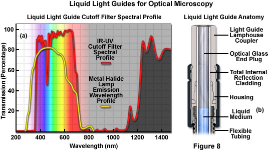
Illustrated in Figure 8(a) is the metal halide lamp spectral profile (yellow curve) measured at the output of a 5-millimeter liquid light guide superimposed on the bandpass regions of a typical cutoff filter (red curve) used in aftermarket lamphouses. Note that the cutoff bandpass filter removes lamp emission wavelengths below 360 nanometers and above 700 nanometers, but is able to pass a significant portion of wavelengths above 1200 nanometers (although emission in this region is minimal for metal halide lamps). The anatomy of a liquid light guide coupler is presented in a cutaway diagram in Figure 8(b). The coupler is fabricated with stainless steel and contains an optical glass end plug that interfaces directly to the liquid medium in the guide. Low refractive index cladding on the inside wall of the flexible tubing ensures that highly oblique light is reflected back into the liquid medium. Coupler design parameters vary by manufacturer (thus lacking an industry standard), making it difficult or impossible to use the liquid light guide designed for any specific aftermarket lamphouse in a competing unit.
Among the most critical issues in using optical fibers and liquid light guides is the efficiency of coupling the source lamp output into the fiber or light guide input tube. Most optical fibers and liquid light guides have a numerical aperture between 0.2 and 0.55, and this value should be matched to the collection optics for the source. Several microscope and aftermarket manufacturers provide metal halide lamphouses designed for implementation with liquid light guides in which this condition is met. The combination of a 75-watt xenon arc lamp or a metal halide lamp in an elliptical reflector, a cold mirror, and an optically matched 3 to 5 millimeter-diameter liquid light guide can deliver a light output in excess of 2 milliwatts per nanometer. The fiber end becomes the effective light source for the microscope regardless of the size of the lamp arc, resulting in a decrease in radiance compared to the arc itself. However, when the goal is uniform illumination of a large-diameter aperture, as is the case in the widefield fluorescence and spinning disk confocal microscopes, an extended source is not as detrimental to performance. The only requirement is a collimating lens of sufficient diameter to efficiently collect the output from the light guide and project it onto the disk scanner or objective rear aperture.
Contributing Author
Michael W. Davidson - National High Magnetic Field Laboratory, 1800 East Paul Dirac Dr., The Florida State University, Tallahassee, Florida, 32310.