
Introduction
In order to provide the necessary contrast and resolution required for the detection of features in live-cell imaging, the microscope must be able to gather sufficient light from the specimen to produce interference that can be interpreted in an informative manner. The vast majority of interesting biological materials, including animal and plant cells, are transparent to visible light, having very few chromatic features or dramatic gradients in refractive index that are capable of generating contrast. Therefore, the successful imaging of living cells and tissues relies on enhancement of contrast using advanced optical techniques, such as phase and differential interference contrast (DIC), Hoffman modulation contrast (HMC), and fluorescence. In designing experiments, a variety of generalized aspects of instrument configuration must be considered. These include the microscope frame style, objective specifications, the illumination source, and the electronic detector system, as well as auxiliary devices such as shutters, filter wheels, and imaging chambers.
Many live-cell imaging systems use a fixed-stage microscope, which is a common feature on research-level inverted (tissue culture-style) microscopes, however, more advanced configurations employ piezo-controlled stages for focusing. The classic fixed stage provides a very stable platform for perfusion and micro-manipulation equipment. In addition, significant changes to coarse focus translate only the nosepiece and do not disturb the specimen or imaging chamber. The inverted microscope also has the advantage that open chambers can be used with the specimen (adherent mammalian cells or plant tissues) secured and flattened against the bottom coverslip. On the contrary, upright microscope frames can be used with water-dipping immersion objectives and this style features a direct port to the image detector, thus avoiding minor light losses through side ports. Modern microscope frames often include motorized focusing, filter wheels, shutters, and objective selection. Although the automation adds convenience, there is nothing inherently "better" concerning the optical performance of an automatic microscope. Instrumentation for maintaining axial focus (termed focus stabilizing mechanisms), which is either laser (or light-emitting diode) based or mechanical, can be extremely valuable for time-lapse investigations, but requires a motorized focus unit.
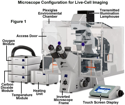
Maintaining living cells in a healthy condition for lengthy periods of time on the microscope stage requires tight control of many environmental variables, including temperature, atmosphere, humidity, osmolarity, and pH. In addition, for optimal imaging, the cells must be housed in a specialized chamber that provides a window (coverslip) matched to the objective design and does not restrict the aperture. A wide variety of original equipment and aftermarket incubator devices are commercially available for this purpose. These range from large Plexiglas chambers that encompass the entire microscope stage (see Figure 1) to small single-dish open and closed vessels that maintain the environment within a much smaller volume.
A generalized live-cell imaging configuration based on an inverted tissue culture microscope is presented in Figure 1. All of the auxiliary components illustrated in the figure are necessary for maintenance of the culture while acquiring images under brightfield, phase contrast, differential interference contrast, and fluorescence illumination. The specimen chamber is positioned on the fixed stage and is usually firmly attached (with the exception of simple microscope slides) over the circular or rectangular stage opening above the objectives. Maintaining the culture chamber environment is a Plexiglas enclosure that encases the microscope condenser system, stage, objectives, and nosepiece. A carbon dioxide sensor and feeder tank valve is controlled by the same unit that monitors the enclosure temperature, while additional units regulate the heating stage and objective heater, which avoids creating a temperature gradient in the region being imaged with immersion oil (not illustrated). The excitation and emission filter wheels and CCD camera system are operated with a separate control unit that is interfaced to the host computer (not illustrated). All of the equipment should be mounted on a breadboard-style vibration isolation platform. Isolation from mechanical disturbance is essential for micro-manipulation, but more importantly, it greatly improves image resolution. Vibration from centrifuges, elevators, autoclaves, and compressors in freezers and refrigerators blurs the image as it is recorded.
Objective Parameters
The most important component for live-cell imaging is the microscope objective and particular attention should be given to the wide range of available choices. Selection begins by identifying the specimen requirements for three parameters: the numerical aperture (NA), the working distance, and the magnification. Of these, the numerical aperture is the most critical feature because this value determines the lateral and axial resolution limits and the amount of light collected (in effect, the available resolution and contrast). Objective numerical aperture ranges from 0.1 to 1.45 with higher values corresponding to greater resolving power. Those objectives considered high numerical aperture (greater than 1.0) have a short working distance (maximum focal distance from the coverslip) and require a special immersion medium, such as water, oil, or glycerin, between the front lens element and the coverslip. The working distance is often overlooked in objective selection, but becomes very important for imaging thicker plant and animal tissue slices. Magnification determines how large the specimen will appear, but can also be considered as a gauge for how much of the specimen area is viewable in the microscope. In general, magnification increases with numerical aperture and decreases with greater working distance.
Microscopes designed since the mid-1990s employ the modern infinity-corrected optical system, which replaces the fixed tube length (usually 160 millimeters) that broadly governed microscope design for most of the twentieth century. Infinity-corrected objectives generally feature higher light transmission, longer working distance, and are not compatible with older microscopes because of the requirement for a tube lens located elsewhere in the microscope frame. Objectives are corrected for chromatic aberration over a wide range from a single focal plane for red and green (achromats) to complete convergence of violet, blue, green, and red (apochromats). Intermediate correction factors are also available. In the lowest correction level, achromats, and even for some highly-corrected apochromat objectives, the axial focus position for blue and ultraviolet light is different from green and red light, even in objectives where differently colored objects co-align in the lateral (x-y) field. This artifact leads to serious problems when determining the relative positions or intensities of two fluorescent probes or when conducting ratio imaging experiments. In addition to chromatic correction, spherical aberrations in the objective can be corrected to achieve a flat visual field (termed plan correction). Almost all modern objectives are also corrected to remove off-axis aberrations, such as coma and astigmatism.
The microscope manufacturers offer a wide variety of objectives having nearly the same numerical aperture, magnification, and working distance. In general, these objective designs incorporate a tradeoff between light transmission efficiency and better optical correction, or the preservation of light polarization. The additional glass lens elements required for correcting chromatic and spherical aberrations tend to lower transmission efficiency (in effect, reduce brightness). In contrast, objectives designed for fluorescence microscopy (appropriately termed Fluor or Fluar) transmit more light over a broader spectral range, but are often poorly corrected for spherical and chromatic aberration. The absolute light transmission efficiency of an objective tends to be a closely guarded manufacturer's secret. Objectives designed for transmitted light (DIC, HMC, and phase contrast) and polarized applications may be highly corrected, but less efficient for light transmission. Polarized light objectives employ strain-free glass components that preserve the azimuth of linear polarization. Phase contrast objectives contain a dense phase ring near the rear focal plane that has only a slight effect on transmission efficiency (5 to 15 percent reduction). In general, fluorescence objectives are the best choice for live-cell imaging, unless high-resolution DIC or polarization is required for the experiment.
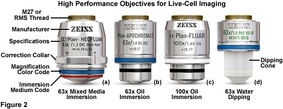
Illustrated in Figure 2 are a series of high-performance objectives designed for, among other applications, producing images having optimal signal-to-noise in live-cell imaging. The 63x plan neofluar mixed media immersion objective in Figure 2(a) is equipped with a correction collar to offset variations refractive index as a function of the immersion medium and to minimize spherical aberration at higher operating temperatures (37° C). The numerical aperture of this objective (1.30), although slightly lower than comparable oil immersion objectives, is sufficient to ensure high resolution imaging at wavelengths spanning the violet into the near-infrared spectral regions. The highly corrected plan apochromat 63x (Figure 2(b)) oil immersion objective has a numerical aperture of 1.4 and produces very bright images in fluorescence imaging mode, but does not exhibit parfocality between visible and near-infrared images. The 100x objective (illustrated in Figure 2(c)) produces high-resolution images with superior chromatic correction (similar to the 63x water and oil immersion versions). For electrophysiology, the 63x water dipping objective (Figure 2(d)) is excellent for high magnification imaging using upright microscope frames in patch-clamping experiments.
The optical design of many objectives requires that they be carefully matched to coverslips having a specific thickness (usually 170 micrometers), a value that is usually inscribed on the barrel of the objective (see Figure 2). Virtually all microscopes constructed for the life sciences are equipped by default with objectives that are corrected to use number 1.5 (170 micrometer thick) coverslips. For critical experiments, coverslips having very strict specifications are available. Inadvertently using a number 1 or 2 coverslip with these objectives can markedly degrade image quality, depending upon the magnification factor. In contrast, objectives designed for electrophysiology studies (Figure 2(d)), termed water dipping, do not require a coverslip. These objectives have a ceramic or composite polymer nosepiece and can be dipped directly into the culture medium (or buffer) while working with a living specimen.
Oil immersion objectives are designed for imaging thin specimens that are attached or firmly pressed onto the coverslip. If a liquid medium resides between the specimen and coverslip, or if imaging through more than 20 micrometers of cell volume, the light-focusing properties of the oil immersion objective begin to degrade, and in the worst case, add noise (improperly focused light) to the image. This concern is very often realized when imaging thick tissue slices and plant specimens. Water and glycerin immersion objectives were developed for such conditions because the hydrophilic immersion medium refractive index more closely matches that of the culture medium and cytosol. Regardless of the fact that water and glycerin immersion objectives have lower numerical apertures (1.2 to 1.3) than oil immersion objectives (up to 1.45; see Figure 2), the signal-to noise ratio and resolution for the image may be significantly improved under live-cell imaging conditions. Flat-field (plan) correction is often poor with these objectives, but a typical laser scanning confocal microscope or imaging camera captures less than the central two-thirds of the viewfield, a region where most objectives feature a flat field, irrespective of the correction factor. In cases where the imaging medium contains sufficient high molecular weight components to significantly alter the refractive index, water should be replaced with the imaging medium between the coverslip and the front lens element (for water immersion objectives) and the correction collar used to correct minor spherical aberration artifacts.
In conclusion, several critical guidelines should be considered when choosing objective priorities for live-cell imaging. In all cases, the investigator should use the highest numerical aperture objective that permits adequate working distance to focus through the features of interest in the specimen. In addition, one should choose the magnification factor that will project only the region of interest from the specimen onto the detector. If the specimen is in direct contract with the coverslip (as is the case for adherent cell cultures) an oil immersion objective will usually provide the optimum light collection efficiency. In cases where a liquid medium exists between the specimen and coverslip, or where the microscope must be focused through a large cell or tissue volume, both the conventional and dipping water immersion objectives usually produce superior contrast at nearly comparable resolution. For objectives that feature a correction collar for eliminating spherical aberration when using varying coverslip thicknesses and immersion media, the optimum setting should be carefully determined. Also, when imaging single fluorophores in live-cell scenarios, it is often wise to choose an objective that features high transmission rather than extensive color correction (which is not necessary for single-color imaging). Finally, applications requiring short (less than 380 nanometers) or long (more than 600 nanometers) illumination wavelengths, as well as polarized light, require specialized objectives having optical materials that remain transparent throughout these regions of the spectrum.
Illumination Systems
In live-cell imaging, the typical microscope illumination system contains a light source, shutters for exposure timing, and filters for selecting both light intensity and wavelength. The goal for illumination of living specimens is to generate a temporally constant, spatially uniform field having defined spectral characteristics for a precise amount of time. In brightfield microscopy (including the contrast-enhancing techniques of DIC, HMC, and phase contrast), light sources include traditional tungsten-halogen lamps and light-emitting diodes (LEDs). The recently introduced LED sources provide a more constant spectrum over their intensity range and generate less heat than incandescent lamps. Fluorescence microscopy requires significantly more intense illumination, typically provided by plasma arc-discharge lamps or a scanned laser beam. The plasma arc lamps, using mercury or xenon as the vapor source, yield sufficient light that a narrow band of wavelengths can be selected using a filter for fluorescence excitation (see Figures 3 and 4). The output from a xenon source is relatively stable and contains a broad, flat spectrum of wavelengths, both of which are important for quantitative applications, such as intensity measurements and ratio imaging. In contrast, mercury arc lamps are very intense, but suffer from flicker as they age and have an irregular spectrum containing sharp output peaks. Newer metal-halide lamps combine several of the best qualities of xenon and mercury lamps.
LEDs are beginning to emerge as a promising illumination technology for live-cell imaging. These versatile semiconductor devices possess all of the desirable features of arc lamps and are efficient enough to be powered by low-voltage switchable supplies, with switching speeds that can dramatically exceed those of mechanical devices, such as filter wheels. The diverse spectral output afforded by LEDs makes it possible to select an individual diode light source to supply the optimum excitation wavelength band for fluorophores spanning the ultraviolet, visible, and near-infrared regions. Furthermore, newer high-power LEDs generate sufficient intensity to provide a useful illumination source for a wide spectrum of applications in fluorescence microscopy, including live cell imaging.
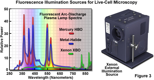
The near-ultraviolet, visible, and near-infrared spectral profiles of three commonly used arc-discharge plasma lamps (mercury, xenon, and metal-halide) are illustrated in Figure 3 along with a commercial stand-alone xenon illumination system. Note the similarity in spectral peaks between the mercury and metal-halide lamps, but the overall higher relative intensity exhibited by the latter source. In contrast, the xenon lamp produces a relatively flat spectrum in the visible region with several minor peaks in the infrared. The xenon illumination system presented in Figure 3 consists of a lamp, housing, cold mirror, and power supply, all contained in a unit that is operated externally and coupled to the microscope with a liquid light guide. The lamp unit is designed to provide intense illumination to the optical train and can accommodate a shutter and/or filter wheel attachment.
The coherent beam of light emitted by most laser sources features specialized properties that can be harnessed for specific applications. A laser produces one or more monochromatic outputs, often termed spectral lines, that are concentrated in a small diameter (usually 0.5 to 3 millimeter) beam. The majority of lasers utilized in optical microscopy imaging systems are either gas filled tubes (such as argon-ion, krypton-argon, or helium-neon mixtures) or solid-state devices. Diode lasers have a potentially longer lifetime with less maintenance, although the power and beam quality of some solid state lasers are often inferior to those quantities observed with gas tube lasers. Laser beams remain collimated over long distances, fanning out less over distance than light generated by a lamp and collimated with a lens. Laser power output is specified in watts (Joules per second) or milliwatts, where specimen illumination is typically in measured in terms of microwatts.
Microscopes targeted at live-cell imaging applications require shutters for the illumination system to limit specimen exposure to harmful doses of light energy. Electro-mechanically operated shutters, precisely timed to the exposure, are the best tools for limiting specimen illumination time when used with arc lamp sources (illustrated in Figure 4(e)), but these devices are not necessary when using newer LED light sources. Be aware, however, that microscope systems not intended for imaging living cells will inadvertently leave the shutter open until the image has been transferred from the detector to a host computer. A seemingly trivial 0.5 second of additional illumination time per exposure can be disastrous for long term time-lapse imaging experiments. A wide variety of aftermarket shutters are commercially available in a number of configurations to retrofit both transmitted and fluorescence optical paths. These devices are readily controlled by popular software acquisition and control packages available from the microscope companies or accessory distributors.
The primary function of an optical filter is to condition the illumination for light frequency (wavelength or color) and/or intensity before it reaches the specimen. The intensity of non-laser illumination sources (arc and tungsten-halogen lamps) should be attenuated with optical density filters whenever possible, and not through adjustment of the electrical power supply driving the lamp. Optical density filters are typically metal-coated glass or quartz disks that reduce light intensity without dramatically altering the color spectrum. While balance filters, which are excellent for photograph film emulsions, are often still incorporated into commercial microscopes, they are less useful for modern digital imaging applications. However, green bandpass filters used in brightfield illumination can improve resolution by limiting the effects of chromatic aberration in objectives having poor correction.
The most critical filters for live-cell investigations are infrared (or heat cut) and ultraviolet filters, which are installed between the illumination source and the specimen in both brightfield and fluorescence pathways. Mercury, xenon, and tungsten-halogen lamps generate sufficient ultraviolet and infrared radiation to damage the specimen, and, in many cases, this harmful light is not blocked by the fluorescence filter cube or polarizers inserted into the optical pathway for DIC imaging. Laser illumination for confocal microscopy or LED illumination for widefield microscopy do not require these filters, but locating specific areas for imaging using unfiltered brightfield or fluorescence illumination on the same microscope can damage the specimen.
Filters designed for selecting a specified bandwidth of light (a limited number of wavelengths) for fluorescence excitation or emission are fabricated by depositing successive layers of quarter wavelength-thick material on optical glass. These interference filter disks are then mounted into a filter wheel or directly into a specialized optical block commonly referred to as a fluorescence filter cube (see Figures 4(a) and 4(b)). Illumination at any single wavelength or narrow band of wavelengths residing in the excitation spectrum results in a wide band of fluorescence wavelengths spanning the entire emission spectrum (a phenomenon known as Kasha's Rule). Therefore, a narrow (approximately 10 to 20 nanometers) bandpass excitation filter is strongly recommended for live-cell imaging of mammalian cells in order to minimize background autofluorescence and in plant cells to limit excitation of endogenous fluorophores and sensory molecules. The investigator should exercise caution in choosing fluorescence excitation filters for imaging living cells and tissues. Often, the pre-packaged filter sets available from the microscope manufacturers and aftermarket distributions contain wide bandpass excitation filters that can increase background fluorescence and introduce excessive levels of detrimental illumination to the specimen. In most cases, narrow bandwidths will serve to sufficiently excite fluorescent proteins and synthetic fluorophores while limiting phototoxicity. However, when target abundance is low or when using very dim fluorophores, larger bandpass excitation and emission filters may help to improve signal-to-noise.
The combination of barrier filters and dichromatic mirrors employed for selecting emission bandwidth is often neglected when attempting to improve the signal-to-noise in the imaging system. The dichromatic mirror requires only a sharp cut-on transition between the excitation (reflected) and emission (transmitted) filter windows. Furthermore, the mirror should feature maximum reflection of excitation wavelengths in addition to minimal attenuation of transmission in the emission spectral region being passed to the barrier filter. Selecting the parameters (bandwidth and spectral profile) for an emission filter is equally important for both widefield and confocal fluorescence applications. The filter passband should closely match the emission spectral profile of the target fluorophore to maximize signal. However, very wide passbands that gather signal over the entire range of a fluorophore emission spectrum (typically ranging from 100 to 250 nanometers) are often crippled by bleed-through from autofluorescence and other fluorophores in multi-color experiments. Therefore, fine-tuning the barrier filter passband is a critical factor in securing the maximum level of signal-to-noise while simultaneously reducing artifacts. In most cases, this effort results in a compromise.
Specialized filter sets containing multiple bandpass interference components are available for simultaneous imaging of two, three, or four fluorophores. However, unless these filters are being employed in multi-color applications with color digital cameras, they are less efficient than single-fluorophore filter sets in terms of signal-to-noise, bleed-through, and other artifacts when using monochrome detectors. A preferable alternative is to use single bandpass filters housed in a motorized filter wheel (Figure 4(d)) for both excitation and emission while retaining a multiple-band dichromatic filter in the microscope filter turret. The increase in signal achieved using single bandpass filters is a tradeoff with an increased likelihood of image misalignment and independent flat-field corrections in two or three color imaging. Ultimately, choosing the best technique for multi-color imaging will depend upon the availability of equipment and the experimental requirements.
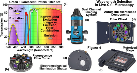
Illustrated in Figure 4 are several aftermarket devices that are useful for wavelength selection in fluorescence microscopy, as well as additional components often found on automated microscopes employed in live-cell imaging. The fluorescence filter spectra presented in Figure 4(a) demonstrate the relationship between the transmission profiles of the excitation, barrier (emitter), and dichromatic mirror components. These filters are usually conveniently housed in an optical block that can be loaded into a turret (Figure 4(b)) along with filter combinations for additional fluorophores. The dual channel imaging system (Figure 4(c)) and 10-position filter wheel (Figure 4(d)) are designed to quickly interchange excitation or emission filters (filter wheel) or to simultaneously gather images from two filter channels. The electromechanical shutter system (Figure 4(e)) and the motorized stage (Figure 4(f)) enable the microscopist to restrict specimen illumination and to rapidly translate from one lateral position to another, respectively. Axial control with automatic stages is useful in deconvolution investigations and is necessary for many commercial autofocus mechanisms.
Detectors for Live-Cell Imaging
Modern imaging of living cells in culture relies heavily on electronic area array detectors, including CCD cameras, as well as high-gain point source detectors, such as photomultiplier tubes (PMTs). Although differing in architectural detail, both the digital camera and the photomultiplier are analog sensors built on a common principle. Photons impinging on a photoactive substrate are converted to photoelectrons and ultimately read out as an analog current or voltage stream. Digitizing the signal, by serially approximating the number of electrons in the stream at specific times, creates a relative gauge of light intensity, free from the progressive accumulation of noise inherent in storing analog data. By correlating the sampling time with the position of the array element or the scanned beam, the intensity values are spatially correlated to recreate an image of the specimen. Detector settings that are user-definable typically include exposure time, readout rate, gain, offset, and selecting a region of interest (a portion of the array) for readout.
In all electronic detectors, signal generation occurs when photons strike the active substrate material on the detector surface. The exposure time and illumination intensity determine the number of photons generated for image formation. The efficiency of converting photons to photoelectrons is governed by the fraction of the detector surface that can sense photons (known as the fill factor in CCDs) combined with the quantum efficiency of the substrate. The quantum efficiency is defined as the number of photons successfully converted divided by the total number impacting the substrate. In addition, the detector material inevitably generates a number of spurious electrons, ominously termed dark current. Cooling the image sensor, often to a range between -20 and -80 degrees Celsius, suppresses the dark current when long exposure times are necessary.
After being collected by the detector, the signal and dark current electrons are read out to an analog-to-digital converter (ADC). Reading the electron output results in an artifact known as readout noise, which occurs either from thermally generated electrons or from small timing errors, and is also directly proportional to readout speed. Together, the dark current and readout noise constitute the principle noise sources in the image recording process, beyond the statistical nature of photon counting (referred to as shot noise). The driver software for many digital cameras permits selection of a readout amplifier speed, usually specified in megahertz (MHz) or pixels per second. Choosing faster readout frame rates results in lower signal-to-noise ratios. Similarly, in confocal microscopy, the beam scanning speed relative to the sampling time of the photomultiplier, can often be altered to increase the signal being read out to the converter.
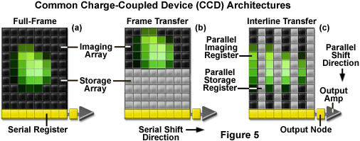
Three basic variations of CCD architecture are in common use for scientific imaging systems: full frame, frame transfer, and interline transfer (illustrated in Figure 5). The full-frame image sensor (Figure 5(a)) has the advantage that nearly 100-percent of its surface is photosensitive, although it must be protected from incident light during readout (usually with an electromechanical shutter). Frame-transfer CCDs (Figure 5(b)) operate faster than the full-frame devices because exposure and readout can occur simultaneously. Although they are similar to their full-frame counterparts in structure, one-half of the rectangular pixel array is covered with an opaque mask that is used for a storage buffer for photoelectrons prior to readout. In contrast, the interline-transfer CCD (Figure 5(c)) contains columns of active imaging pixels along with masked storage-transfer pixels that alternate over the entire array. Because a charge-transfer channel is located immediately adjacent to each photosensitive pixel column, stored charge must only be shifted a short distance, rendering these chips the fastest in terms of readout. A majority of the color and cooled monochrome scientific digital cameras are equipped with interline-transfer image sensors, however, more advanced electron-multiplying CCDs (discussed below) typically contain frame-transfer chips.
The analog-to-digital converter samples the sensor readout over a tightly controlled timer interval, which is synchronized with the readout amplifier. This stage is where the photoelectrons and noise electrons from the detector are converted to a gray level or intensity value. The converter has an input range that limits the total number of electrons before saturation (white), and a set number of electrons that are required for creating each gray level. The term bit depth refers to the binary range of possible grayscale values employed by the converter to translate analog image information into discrete digital values capable of being read and analyzed by a computer. For example, the most popular 8-bit digitizing converters have a binary range of 2(E8) or 256 possible values, while a 10-bit converter has a range of 2(E10) (1,024 values), and a 16-bit converter has 2(E16), or 65,536 possible values. The bit depth of the analog-to-digital converter determines the size of the gray scale increments, with higher bit depths corresponding to a greater range of useful image information available from the camera. Another important concept, the dynamic range is typically specified as the maximum achievable signal divided by the camera noise, where the signal is determined by the full-well capacity (maximum of photoelectrons that each pixel is capable of holding), and the noise is the sum of dark and readout noises. As the dynamic range of an image sensor is increased, the ability to quantitatively measure the dimmest intensities is improved.
A detector with 4 electrons of system noise probably uses at least four electrons for each gray level and would require an input range of 16,384 (4(E12)) electrons to be digitized to 12-bit resolution. Note that for some image sensors (especially CCDs) with 12-bit (4096 gray levels), 14-bit (16,384 gray levels), or even 16-bit (65,500 gray levels) converters, the image detector material may not have sufficient full-well capacity to fill the entire analog-to-digital converter input range under all circumstances. In this case, more gray levels are generated by the analog converter than correspond to actual photoelectrons obtained from the detector. This is often the situation with commercial monochrome camera systems that digitize image data above 10-bits. The importance of having the high converter bit depths lies in the ability to capture real differences in signal intensity (in effect, contrast), even if the effort of doing so requires a smaller number of gray levels than are available to the sensor.
The signal from the digital camera or photomultiplier can be matched to the input range of the analog-to-digital converter by carefully setting the gain and offset parameters, as well as the readout amplifier speed. For example, if two adjacent pixel elements that have collected 101 and 109 electrons, respectively, are fed into an 8-bit converter with an input range of 2560 electrons, then 10 electrons would be required for each gray level. With no electronic gain, the adjacent pixels would have identical values (a grayscale level of 10) in the final image. If the combined detector noise for this system is only 2 electrons, the counts of 101 and 109 should be distinguishable. Applying a gain of 5 (a multiplicative process) yields 505 and 545 electrons, respectively, now sampled to values of 50 and 54 by the converter. Thus, the gain amplifier has increased the difference in the detector value such that it can now be interpreted by the analog converter as separate values. Because, in this hypothetical case, a gain factor of 5 would push any detector value greater than approximately 500 out of the converter input range, the offset control can be used to subtract electrons prior to digitization. Subtracting 400 electrons in the example above leaves 105 and 145 electrons, sampled to values of 10 and 14 in the resulting image. In practice, the gain amplifier introduces noise in proportion to the gain factor, limiting the effective multiplier.
In practice, the detector and illumination aperture should be adjusted to gather light from the smallest possible area of the specimen that still contains the information required for feature identification and context. Imaging a larger area increases specimen exposure to illumination and lengthens the sensor readout time. For digital cameras, the readout area can be set using the accompanying software package that controls acquisition. Matching the resolution of the objective to the image sensor resolution should also be taken into account. Laser scanning confocal microscopes also enable software-selectable areas for image acquisition, cleverly disguised as a zoom function. When using this feature, be aware of the interplay between the zoom factor and the spatial sampling rate, which is often recalculated by the microscope software. In cases where selecting a small area to image does not change the number of samples (pixels) proportionately, then the goal of shortening the illumination and readout time has not been achieved. In this situation, the image size should be reset with the sampling rate, bearing in mind the resolution limits of the objective.
Modern Image Detectors
Although the same basic principles apply to most of the detectors commonly used in optical microscopy, commercial implementations differ markedly. The key design feature of the CCD-based camera is that it stores electrons during exposure, without accumulating substantial noise, providing exceptional dynamic range. The exposure time and the readout rate are the critical parameters. CCD sensor elements (photodiodes) simulate photoelectron collection buckets, starting with zero electrons and filling to a defined saturation point, termed the full-well capacity, as discussed above. In the most refined camera systems, the well depth is closely matched to the analog-to-digital converter input range, precluding the requirement for user controlled gain and offset parameters. In addition, selectable readout amplifier speeds enable compromises between signal-to-noise and the maximum frame rate.
An additional virtue of the digital camera is the high quantum efficiency of research-grade systems, which can reach approximately 90 percent in back-thinned devices (where the rear surface of the CCD is thinned and illuminated). Furthermore, the excellent response linearity enables the output signal to be tightly correlated with photon counts over the entire dynamic range. The important advantages of the CCD camera are exploited in three fundamental concepts:
Long exposures can be used to collect light from a weak signal source for detection.
The dynamic range permits local contrast differences within bright and dim features
to be captured in the same image.The response linearity simplifies the background subtraction and calculations required
for quantitative applications.
Traditionally, a video camera has referred to a vacuum tube device, while a digital or scientific camera is reserved for modern solid state (CCD) imaging systems. Although most video cameras now use solid-state chips, an important difference still persists with the jargon. Typical video cameras, engineered to output 30 frames per second, sacrifice sensitivity and resolution for cost and speed. A video camera can be used for brightfield microscopy, but quantitative assessments of relative intensity differences may be stymied by auto-gain or gamma-correction circuits, and in some cases, the image suffers from geometrical distortions due to non-square pixel dimensions. Consumer video cameras should, if at all possible, be avoided for serious efforts in optical microscopy.
Full-color digital cameras segregate the red, green, and blue (RGB) portions of the visible spectrum into separate images and blend them together after exposure to simulate color vision. Video rate cameras incorporate a color mask that is printed over the image sensor CCD, lowering resolution by a factor slightly greater than 3, even for the best cameras. More advanced color cameras either collect three consecutive images using a filter wheel (or liquid crystal tunable filter; LCTF) to select color bandwidth, or have three sensor chips coupled to a mechanism for dividing the incoming light into red, green, and blue channels for simultaneous acquisition. The application of color cameras to live-cell imaging, except in very specialized circumstances, has been hampered by the lack of acquisition speed, sensitivity, dynamic range, and resolution. Notable exceptions are newly designed multi-chip cameras that have proven useful in ratio-imaging and resonance energy transfer (FRET) investigations.
Photomultipliers (and related devices), in general, demonstrate relatively moderate quantum efficiency, rising only to 40 percent in the best cases, and generate a large number of spurious electrons (noise) compared to area array (CCD) detectors. The photomultiplier does not typically store charge, but rather applies high gain and variable offset controls to boost the signal above noise levels. The principal advantage of photomultipliers is the ability to measure the rapidly changing intensity of a point source, such as the specimen fluorescence resulting from a scanned laser beam. For each successful photoelectron conversion by the light-sensitive photocathode, the photomultiplier amplifies the signal into many hundreds or thousands of electrons before sampling by the analog-to-digital converter. Rapid sampling, usually on a microsecond scale, reduces the effects of dark current accumulation, and applying a massive gain to the signal before readout minimizes the impact of readout noise. Therefore, signal-to-noise ratios for photomultiplier systems are typically dominated by the photon counting variance, shot noise. Taking advantage of the gain and offset controls of a photomultiplier allows extraction of meaningful dynamic range from laser scanning confocal and multiphoton microscope systems.
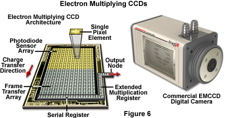
In conclusion, over the next few years, the microscopists are likely to encounter a wide variety of new detection systems using advanced technology. For example digital cameras employing complementary metal oxide semiconductor (CMOS) sensors have displaced many CCD technologies in the consumer market, but the poor quantum efficiency (approximately 25 percent), fill factor, and random pattern noise (an artifact introduced by multiple independent amplifiers in each pixel) presently limits usefulness in low-light applications for scientific work. Intensified CCD cameras (termed ICCDs) are comprised of an array of micro-photomultipliers installed in a microchannel plate that is usually fused to the sensor chip. The microchannel plate limits spatial resolution and response linearity, but provides excellent signal detection capabilities when high frame rates are critical. Electron multiplying CCD cameras (EMCCDs; Figure 6) have a gain amplifier built into the CCD chip, enabling multiplication of the signal electrons prior to the addition of readout noise. These cameras, which are rapidly emerging in the live-cell imaging arena, provide all of the fundamental virtues of a standard scientific camera, with the additional property that fewer photoelectron conversions need to take place before the analog converter can transform the signal into a usable dynamic range. Solid-state alternatives to the photomultiplier have been employed for many years and include specialized CCD units and avalanche photodiodes.
Contributing Authors
Sidney L. Shaw - Department of Biology, Indiana University, Bloomington, Indiana, 47405.
Matthias F. Langhorst - Carl Zeiss MicroImaging GmbH, Koenigsallee 9-21, 37081 Goettingen, Germany.
Michael W. Davidson - National High Magnetic Field Laboratory, 1800 East Paul Dirac Dr., The Florida State University, Tallahassee, Florida, 32310.