


On upright microscopes, the condenser is located beneath the stage and serves to gather wavefronts from the microscope light source and concentrate them into a cone of light that illuminates the specimen with uniform intensity over the entire viewfield. It is critical that the condenser light cone be properly adjusted to optimize the intensity and angle of light entering the objective front lens. Each time the objective is changed, a corresponding adjustment must be performed on the condenser to provide the proper light cone to match the numerical aperture of the new objective. The size and numerical aperture of the light cone is determined by adjustment of the aperture diaphragm. After passing through the specimen, the light diverges into an inverted cone with the proper angle to fill the front lens of the objective.
The tutorial initializes showing an abbreviated version of the microscope optical train containing an objective, specimen, condenser, and aperture diaphragm. The condenser numerical aperture is set to 0.25 and the light cone leaving the condenser is focused on the specimen. In order to operate the tutorial, use the Magnification slider to increase the condenser numerical aperture and observe how opening the iris diaphragm increases the size of the light cone.
The design of an optical microscope must ensure that the light rays are organized and precisely guided through the instrument. Illumination of the specimen is the most important controllable variable in achieving high-quality images in microscopy, critical photomicrography, and digital imaging. Any lack of brightness is not a problem in simple brightfield microscopy, but if contrast-enhancing techniques, such as phase contrast, differential interference contrast, fluorescence, or polarization contrast are used, additional optical elements that consume a significant portion of the available light flow are inserted into the beam path. Such a situation leaves little light for observation, and as a result, the images assume a dark character. When properly adjusted, light from the condenser will fill the rear focal plane of the objective with image-forming light by projecting a cone of light to illuminate the field of view. The condenser aperture diaphragm is responsible for controlling the angle of the illuminating light cone and, consequently, the numerical aperture of the condenser. This concept is illustrated in Figure 1, where a series of condensers are illustrated with light cones (and numerical apertures) of decreasing size from left to right in the figure.
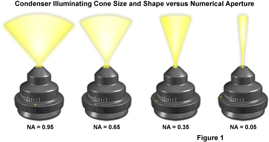
Another reason for the existence of fixed and adjustable diaphragms, prisms, beamsplitters, and filters in the microscope is that the illumination often must be reset after each change of the objective. This is, in part, because the size of the observed specimen field changes with every objective magnification. An objective with a low magnification (for example, 4x) provides a large field of observation (with a diameter of as high as 5 millimeters in this case, provided that the eyepiece permits an intermediate image of diameter 20 millimeters). If a switch is made to the 40x objective, the diameter of the viewfield of the specimen shrinks by the factor 10 (to only 0.5 millimeters). The viewable area then becomes as much as 100x smaller. The second reason is that the numerical aperture increases from 0.12 to 0.65 or, expressed as aperture angles, from 15 degrees to 80 degrees. The effect of numerical aperture on illumination light cone size and shape is presented in Figure 1.
Aperture adjustment and proper focusing of the condenser (with regard to height in relation to the objective) are of critical importance in realizing the full potential of the objective. Specifically, appropriate use of the adjustable aperture iris diaphragm (incorporated into the condenser or just below it) is of significant importance in securing correct illumination, contrast, and depth of field. The opening and closing of this iris diaphragm controls the angles of illuminating wavefronts (and thus the aperture size) that bathe the specimen. Condenser height is controlled by a rack and pinion gear system that allows the condenser focus to be adjusted for proper illumination of the specimen. Correct positioning of the condenser with relation to the cone of illumination and focus (a step in establishing Köhler illumination) is critical to quantitative microscopy and to ensure the best digital images.
Condensers are divided primarily into classifications of imaging modality (such as brightfield, darkfield, and phase contrast), but also according to their degree of optical correction. There are four principle types of condensers with respect to correction of optical aberrations, as listed in Table 1. The simplest and least corrected (also the least expensive) condenser is the Abbe condenser that can have a numerical aperture up to 1.4 in in the best models with three or more internal lens elements. Although the Abbe condenser is capable of passing bright light, it is not corrected for either chromatic or spherical optical aberrations. A typical Abbe condenser is illustrated in Figure 2. In its simplest form, the Abbe condenser has two optical lens elements that produce an image of the illuminated field diaphragm that is not sharp and is surrounded by blue and red color at the edges, characteristic of chromatic aberration.
The next level of condenser sophistication is split between the aplanatic and achromatic condensers that are corrected exclusively for either spherical (aplanatic) or chromatic (achromatic) optical aberrations. Achromatic condensers usually contain three to four lens elements and are corrected in two wavelengths (red and blue) for chromatic aberration. The achromatic condenser usually contains four lens elements and has a numerical aperture ranging from 0.95 to 1.4. This condenser design is useful for both routine and critical laboratory analysis with "dry" or oil immersion objectives and also for black and white or color photomicrography and digital imaging. The highest level of correction for optical aberration is incorporated in the aplanatic-achromatic condenser. This condenser is well corrected for both chromatic and spherical aberrations and is the condenser of choice for use in critical color imaging with white light. A typical aplanatic-achromatic condenser features eight internal lens elements cemented into two doublets and four single lenses.
Aberration Correction in Condenser Optical Systems
|
|||||||||||||||||
Table 1
Engravings found on the condenser housing include its type (achromatic, aplanatic, etc.), the numerical aperture, and a graded scale that indicates the approximate adjustment (size) of the aperture diaphragm. Condensers with numerical apertures above 0.95 perform best when a drop of oil is applied to their upper lens in contact with the undersurface of the specimen slide. This ensures that oblique light rays emanating from the condenser are not reflected from underneath the slide, but are directed into the specimen. In practice, this can become tedious and is not commonly done in routine microscopy, but is essential when working at high resolutions and for accurate imaging using high-power (and numerical aperture) objectives.
When the objective is changed, for example from a 10x to 20x, the aperture diaphragm of the condenser must also be adjusted to provide a new light cone that matches the numerical aperture of the new objective. This is done by turning the knurled knob or lever that controls the condenser aperture diaphragm. There is a small yellow or white dot, arrow, or index mark located on the condenser that indicates the relative size of the aperture when compared to the linear gradation on the condenser housing. Many manufacturers will synchronize this gradation to correspond to the approximate numerical aperture of the condenser. For example, if the microscopist has selected a 10x objective of numerical aperture 0.25, then the arrow would be placed next the value 0.18-0.20 (about 80 percent of the objective numerical aperture) on the gradation inscribed on the condenser housing.
Contributing Authors
Christopher E. Steenerson and Michael W. Davidson - National High Magnetic Field Laboratory, 1800 East Paul Dirac Dr., The Florida State University, Tallahassee, Florida, 32310.