


The principle concept behind aperture correlation is to overcome the pinhole crosstalk limitation by using temporal rather than spatial coding. In effect, instead of probing each pixel only once with a spatially uniquely positioned pinhole, the idea is to probe each pixel multiple times but with a temporally unique sequence. Each pixel is presented with a sequence of pinhole illuminations that shows zero cross correlation to the sequence presented to any other pixel. Thus, for each pixel in the image, a temporal modulation of an aperture transmission according to an appropriate correlation sequence must be found (thus the name aperture correlation). The temporal coding necessary for aperture correlation can be achieved by a dense, random pattern of pinholes on a rotating disk. In this manner, each pixel will be probed several times through different pinholes, but for each pixel the illumination sequence will be random, and thus unique. A major limitation is that such an instrument cannot directly provide a confocal image as this would require negative transmission values for the blocking areas of the disk. In reality, the image detected through the disk contains all the in-focus information plus an offset representing out-of-focus information.
The tutorial initializes with a drawing of the ZEISS VivaTome optical train presented in the main window with the excitation and emission (both transmitted and reflected) light paths indicated. The specimen appears in the Raw Data Image window. In order to operate the tutorial, click on the Filter Wheel Position radio buttons to toggle between blue, green, and red fluorescence emission. The Excitation and Emission light path checkboxes can also be used to examine these pathways more closely.
The principal lay-out of the ZEISS VivaTome, a commercially available aperture correlation spinning disk system, is presented in Figure 1. A rotating disk having a defined grating pattern is located in one of the microscope conjugate image planes. Excitation light is directed through this disk, and the transparent regions on the disk are placed very close together so that approximately 50-percent transmission efficiency through the disk is achieved. As a result, any normal white light source (such as a metal halide lamp) will provide sufficient excitation intensity.
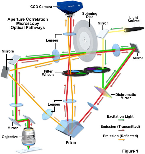
Emission from the sample is again directed to the disk through the optical train, and the emission light from the focal plane will be focused through the openings on the disk and subsequently onto the detector. However, because to the disk layout features densely packed openings, out-of-focus light will also randomly pass through the disk (see above). With a 1:1 line-to-space ratio (50 percent of the disk being transmissive), 50 percent of the out-of-focus light will make it through random openings in the disk. Thus, the image detected through the disk contains all the in-focus information but also 50 percent of the out-of-focus information. In order to capture the additional information needed to calculate an optical section disk positioning geometry is critical. The disk is positioned at a slight angle to the optical pathway, and the side facing the specimen is reflective. This architecture enables the out-of-focus light normally blocked at the disk to be reflected into a second imaging beam path that is finally imaged onto the camera side-by-side with the image detected through the disk. In the second image, the other 50 percent of the out-of-focus light is captured. Using the side-by-side detection strategy for both images, all the information needed to calculate the optical section is captured simultaneously on one camera and motion artifacts can be excluded.
Contributing Authors
Tony B. Gines and Michael W. Davidson - National High Magnetic Field Laboratory, 1800 East Paul Dirac Dr., The Florida State University, Tallahassee, Florida, 32310.