


The most advanced design in spinning disk instruments was engineered by Yokogawa Electric Corporation of Japan and implemented in a series of increasingly complex disk scanning units. These scanners are equipped with a unique architecture that consists of two coaxially aligned disks featuring a dichromatic mirror positioned between the disks (see the tutorial). Each disk contains approximately 20,000 pinholes (with a 250-micrometer spacing) arranged in a series of nested spirals. The upper disk is actually a glass plate containing Fresnel microlenses on the top surface that direct and focus light onto perfectly aligned 50-micrometer pinholes in the lower disk for transmission to the objective and specimen.
The tutorial initializes with an animated cartoon of the Yokogawa optical system in the left-hand portion of the window and images of the specimen and the scanning pattern on the CCD surface on the right-hand side. In order to operate the tutorial, use the Disk Speed slider to increase or decrease the rotation speed of the dual disks and observe how it affects the CCD window. The Z-Depth slider can be used to scan through the specimen along the axial plane. New specimens can be chosen using the Specimen pull-down menu.
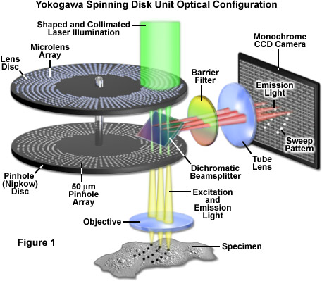
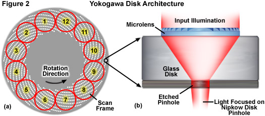
Presented in Figure 1 is a schematic diagram of the basic optical configuration in Yokogawa scanning units. Laser light introduced into the scanner through a single mode optical fiber is shaped by a specialized lens to adjust the intensity distribution of the Gaussian beam towards the center and is then projected onto the microlens disk with a collimating lens (illustrated as green light). Individual microlens elements gather a substantial amount of the incoming light (see Figure 2) and focus it through the dichromatic beamsplitter onto an area covering approximately 1,000 pinholes on the lower Nipkow disk (an area spanning 7 x 10 millimeters). The pinhole spiral patterns are designed so that a single image is created with each 30-degree rotation of the disk. Because the radial scan pitch between adjacent spirals is organized into a pattern that slightly offsets adjoining pinholes, the specimen is fully raster-scanned by partially overlapping images of the pinholes.
Depending upon the unit model, the Yokogawa confocal scanners have maximum disk rotation speeds of 1800 (CSU-10), 5000 (CSU-22), and 10,000 (X1) revolutions per minute, with the pinhole array pattern scanning 12 frames during each 360-degree rotation (see Figure 2(a)). These factors yield a theoretical maximum frame rate of 360, 1000, and 2000 frames per second, respectively. Although the model 22 is no longer being produced, there are likely to be a significant number of model 10 and 22 scanners remaining in the field for several years to come. Yokogawa is currently marketing the CSU-X1, which can be outfitted with two filter wheels (using two cameras) or a single filter wheel with or without an auxiliary unit that enables sequential capture of brightfield (and phase contrast or differential interference contrast; DIC) images on a single camera. The integrated filter wheels have minimal switching speeds of 33 milliseconds, which limits the acquisition speed of dual color images on a single camera unless multi-band emission filters are used (which in turn may result in bleed-through between emission channels). In practice, operation of the spinning disk unit at rates above 200 frames per second requires careful synchronization between the disk speed and camera integration time so that the pinholes traverse an integral number of frame crossings during exposures. Furthermore, considering the dimly fluorescent specimens commonly encountered in live-cell imaging, camera exposure time, rather than disk speed, often becomes the limiting factor in image acquisition rates. For example, using an electron-multiplying CCD (EMCCD) on a weakly fluorescent specimen at an exposure time of 100 milliseconds (quite common using fluorescent proteins in living cells) limits the rate of acquisition to 10 frames per second.
After exiting the pinholes, the individual beams of excitation light enter and fill the objective rear aperture and are projected as a reduced image in the specimen focal plane. Fluorescence emission from the specimen is captured by the objective and focused back onto the pinhole Nipkow disk, where each conjugate pinhole now serves as a confocal exit pinhole and blocks emission from regions of the specimen not residing in the focal plane. Thus, light illuminating the specimen from a particular pinhole creates fluorescence that is gathered by the same pinhole and passed to the dichromatic beamsplitter. Because the Yokogawa beamsplitter must pass short wavelengths (excitation) and reflect long wavelengths (emission), it acts in a manner opposite to typical dichromatic mirrors used in widefield fluorescence microscopy. The emission light reflected from the beamsplitter is passed through a barrier filter to remove any remaining stray light and out-of-band fluorescence before being focused on to the surface of the CCD array of the camera system to generate an image.
As described above, the pinhole patterns in the 55-millimeter diameter Yokogawa Nipkow disk are arranged in a series of nested spirals (see Figure 2) that complete a single scan of the specimen for every 30-degree rotation. Therefore, a complete 360-degree rotation of the disk is capable of generating 12 frames, or 2,000 images per second at the highest disk speeds. The unique disk pinhole pattern provides image frames that are homogeneously illuminated and traced evenly across the specimen by uniformly spaced scan lines. As a result, the images produced by the Yokogawa spinning disk unit are free of light intensity gradients across the field of view and do not suffer from scan line inhomogeneity, typically referred to as scanning stripes. The advanced beam shaping and collimating lenses used in the CSU-X1 substantially increase the light throughput of the scanning unit to enable imaging with reduced laser power. This results in a reduction of the fluorophore photobleaching rates (compared to laser scanning and widefield fluorescence), which allows imaging for extended periods of time.
Due to the fact that camera exposure times are dependent upon the intensity of fluorescence emission gathered by the specimen, and vary widely from one sample to another, the disk rotation speed must be carefully adjusted to match the camera exposure time. Thus, uniform image capture can only be performed if the exposure time is an integral multiple of the time necessary to sweep one scan frame (30 degrees of disk rotation). In cases where the exposure time is not matched (in effect, is not an exact multiple of the rotation speed), scanning will continue into the next frame and can produce a striped pattern superimposed on the image. This artifact is generally not a problem for long exposure times (greater than 100 milliseconds) where averaging occurs between frames, but can seriously hamper imaging success when exposure times are reduced to a few milliseconds. Fortunately, even though the Yokogawa disk is capable of producing 12 images from each 360-degree rotation (see Figure 2(a)), these individual segments do not have defined start and stop points so that any exposure corresponding to one twelfth of a disk rotation will capture a complete image irrespective of the point at which the exposure was started. The Yokogawa CSU-X1 features an advanced disk drive motor that allows for fine-tuning the adjustment of rotation speed to match the camera exposure time. Furthermore, the unit incorporates a dynamic balancing mechanism for the rotating parts to prevent vibrations (as well as accompanying imaging artifacts) that might occur at the highest speeds.
A number of advanced accessories designed to enhance performance are available for the Yokogawa CSU-X1. The high-end scanning unit versions are equipped with a computer-controlled dichromatic mirror changer that enables the user to select between three mirrors, and the 6-position auxiliary filter wheels feature stepping motors, lightweight pulleys, and a timing belt to maintain synchronization. The brightfield light path housing can be used to sequentially capture images in a variety of contrast-enhancing modes, including widefield fluorescence generated via an arc-discharge lamp attached to the microscope. The optical train of the brightfield unit bypasses the spinning disk system and sends images generated by the microscope directly to the camera via a series of relay lenses and mirrors. However, the switching speed of this option is approximately 2 seconds, which renders it the slowest system component for many applications. Additionally, a second camera port can be installed on the scanner so that simultaneous two-color imaging can be performed without the time delay incurred by using the filter wheel. A second dichromatic mirror is installed in the rear of the unit to divide the fluorescence emission received from the primary dichromatic into two discrete wavelength bands that are transferred to the individual cameras. The two-camera configuration provides the fastest action for capturing dual-color images of specimens labeled with, for example, enhanced green fluorescent protein (EGFP) and mCherry, an orange-red fluorescent protein.
The strategy of using massively parallel spinning disk illumination to visualize dynamic events on a variety of timescales in live-cell imaging has proven to be an indispensible tool in cell biology. Although the number of commercially available scanning unit designs is currently limited, this technology should continue to progress with incremental improvements in performance. The Yokogawa scanning unit concept is currently the most advanced Nipkow disk-based design yet implemented, and is capable of generating images of faintly fluorescent specimens with high temporal and spatial resolution. As the microscope companies address new designs targeted at fast live-cell imaging, there will no doubt continue to be advancements in spinning disk and related technologies. An alternative to the Nipkow disk concept is based on sweeping the specimen along both lateral axes with line-shaped excitation illumination. Termed line scanners, these instruments are also capable of high temporal resolution (but at the cost of somewhat reduced spatial resolution). Several commercial line-scanning instruments are being field tested as this promising concept also warrants further development.
Contributing Authors
Adam M. Rainey and Michael W. Davidson - National High Magnetic Field Laboratory, 1800 East Paul Dirac Dr., The Florida State University, Tallahassee, Florida, 32310.