


Introduction
Illumination of the specimen is the most important variable in achieving high-quality images in microscopy and critical photomicrography or digital imaging. Köhler illumination was first introduced in 1893 by August Köhler of the Carl Zeiss corporation as a method of providing the optimum specimen illumination. The manufacturers have designed modern microscopes so that the collector lens and any other optical components built into the base of the microscope will project an enlarged and focused image of the lamp filament onto the plane of the aperture diaphragm of a properly positioned substage condenser. Closing or opening the condenser diaphragm controls the angle of the light rays emerging from the condenser and reaching the specimen from all azimuths. Because the light source is not focused at the level of the specimen, the light at specimen level is essentially grainless and extended, and does not suffer deterioration from dust and imperfections on the glass surfaces of the condenser. Opening and closing of the condenser aperture diaphragm controls the angle of the light cone reaching the specimen. The setting of the condenser's aperture diaphragm, along with the aperture of the objective, determines the realized numerical aperture of the microscope system. As the condenser diaphragm is opened, the working numerical aperture of the microscope increases, resulting in greater resolving power and light transmittance. Parallel light rays that pass through and illuminate the specimen are brought to focus at the back focal plane of the objective, where the image of the variable condenser aperture diaphragm and the image of the light source will be seen in focus.
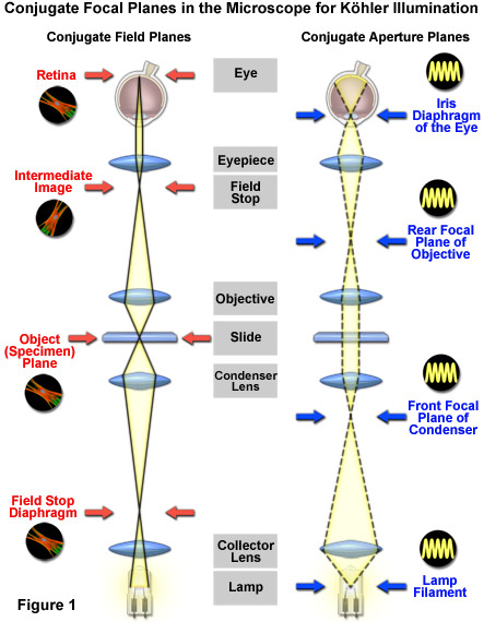
Proper configuration of the microscope in regards to illumination is possibly one of the most misunderstood concepts in optical microscopy, and is a critical parameter that must be fulfilled in order to achieve optimum performance. The intensity and wavelength spectrum of light emitted by the illumination source is of major importance, but even more imperative is that light emitted from various locations on the lamp filament be collected and focused at the plane of the condenser aperture diaphragm. The conjugate field and aperture planes critical for establishing proper illumination in the microscope are illustrated in Figure 1. In this section, the guidelines are described for establishing Köhler illumination (used in transmitted and reflected light microscopy). Successful observation and imaging should occur when this procedure is executed correctly.
The first steps necessary to prepare the microscope for Köhler illumination involve basic procedures necessary to observe a specimen under brightfield conditions. First, if the condenser contains phase annulus rings, differential interference contrast prisms, or other masks and filters, rotate the turret to the brightfield aperture, which should be open and not house a filter or prism. Second, choose a suitable specimen. The best specimens consist of well-stained brightfield samples, such as very thin (8 micrometer or less) animal or plant tissue. If a prepared slide is not available, a small section of 35-millimeter film (such as a transparency or negative) about 10 x 10 millimeters in size can be taped or glued to a clean glass microscope slide and flattened with a cover slip.
Steps in Establishing Köhler Illumination
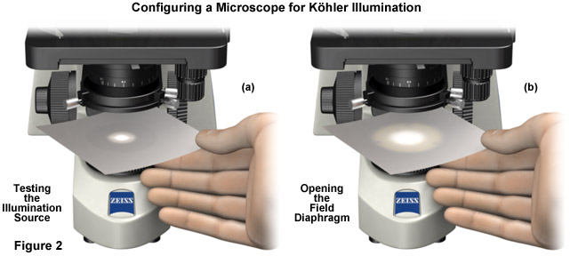
- Switch on the light source and hold a small sheet of paper directly above the luminous field diaphragm collector lens in the base of the microscope (Figure 2(a)). The purpose of this exercise is to check whether the light source is functioning and will project light into the microscope. In cases where no light is observed and the paper remains dark, check the line cord, illuminator, and perhaps the fuse in the power unit to ensure that the electrical components are intact. If not, change the illuminator lamp. When the microscope is operating normally, a small spot of light (Figure 2(a)) will be visible on the paper.
- Next, open the field diaphragm to its widest position (fully open) by turning the lever or knob. The spot of light projected onto the paper sheet (Figure 2(b)) will achieve its maximum diameter.
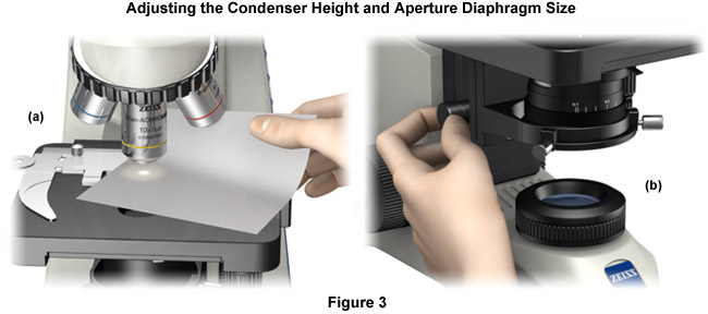
- The next step is to move the sheet of paper and place it between the specimen and the objective (Figure 3(a)) and fully open the condenser aperture diaphragm (usually controlled by a lever or knurled knob located on the condenser housing. As the condenser diaphragm is slowly opened, the intensity of light projected onto the paper sheet will increase, achieving its maximum brightness at the fully opened setting. When using a low numerical aperture condenser equipped with a swing-in front lens element, remove the swing-lens from the light path before attempting this procedure.
- The condenser height can be adjusted using the drive knob that translates this component up and down along the microscope optical axis (Figure 3(b)). Set the condenser height so that the front lens is approximately 1 to 3 millimeters beneath the lower surface of the specimen slide. Make certain the condenser front lens does not contact the slide (or push it up away from the stage). In extreme cases, driving the condenser into the specimen will result in the sample being ejected from the stage when it slips free from the retaining guide. Modern microscopes are often equipped with an adjustable stop screw that allows the top position of the condenser to be fixed at a pre-determined height.
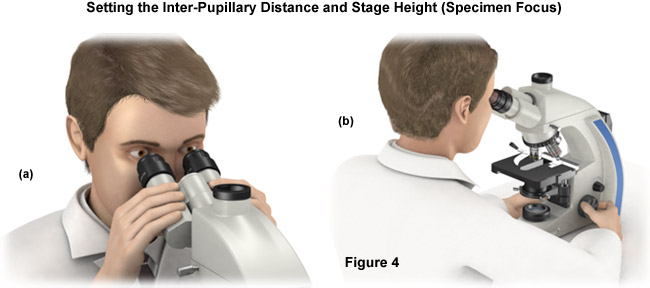
- Light should now be discernable in the microscope eyepieces (Figure 4(a)). If the light is too bright (often bright enough to cause discomfort), reduce the intensity until you find a level that is comfortable to work with. Next, set the interpupillary distance via the folding bridge of the binocular tubes. This can be done by squeezing the tubes together to decrease the distance or pulling the tubes apart to increase the separation between them. The correct distance is reached when a single large circle of light (instead of two) can be easily visualized through the eyepieces. The next step is to check to see if the microscope is equipped with focusing eyepieces. If so, turn the movable eyepiece to the zero setting. Eyeglass wearers can leave their glasses on.
- Peer into the microscope and carefully move the stage, including the specimen, up and down until you see the image details as sharply as possible (Figure 4(b)). At this point, there may be bright and dark spots or part of a diaphragm obscuring the viewfield, as the illumination configuration is still not complete.
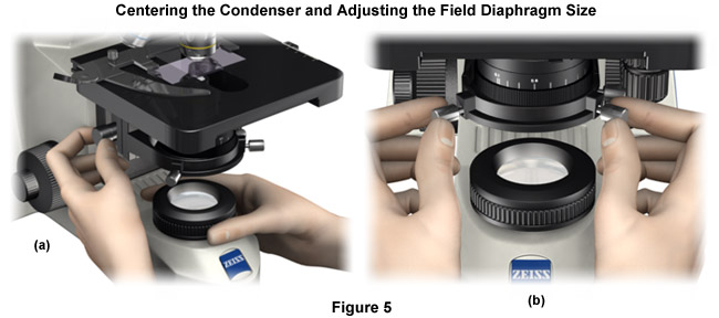
- Now that the basic components of the microscope are set, the instrument is ready to be configured for Köhler illumination. The first step is to narrow the size of the field diaphragm and translate the condenser up and down via the adjustment knob until you see a sharp image of the edges from field diaphragm leaves (Figure 5(a)). If this strategy doesn't work, change the size of the field diaphragm and try again. In many cases, the condenser is not yet centered so only one edge of the viewfield will contain elements of the field diaphragm leaves.
- At this stage, the field diaphragm is in sharp focus, but the condenser is not yet centered. The centering knobs on the microscope condenser mounting frame are used to center the condenser (Figure 5(b)). Close down the field diaphragm to its smallest opening and use the centering screws to relocate the bright opening to the center of the viewfield (a crosshair reticule is very useful for determining the center of the viewfield). Once the condenser is centered, open the field diaphragm until its leaves move completely out of the viewfield.
- At this point in the procedure, you should almost have a suitable image in the viewfield. The only remaining task is to optimize the contrast. Remember that you first opened the aperture diaphragm of the condenser in order to see more light (discussed above). The aperture size must now be corrected in order to improve contrast and to seek a suitable balance between contrast and resolution. Remember that closing the condenser aperture too far will seriously degrade resolution and significantly darken the image.
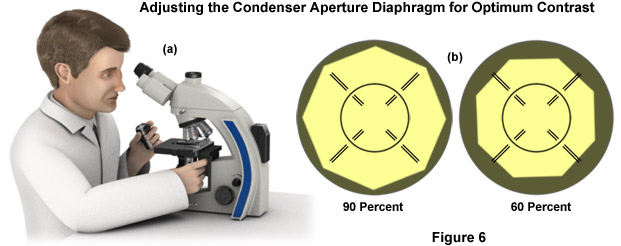
- You can directly visualize the aperture diaphragm superimposed over the objective rear focal plane (objective pupil) if you remove an eyepiece from the binocular tube mount and peer directly into the tube (Figure 6(a)). Your eye should be between 10 and 20 centimeters away from the tube for the best observation. While looking down the tube, open and close the condenser aperture diaphragm until you can clearly recognize the image in the objective pupil. Finally, set the diameter of the diaphragm in such a manner that it illuminates between 65 and 80 percent of the pupil diameter (see Figure 6(b)), providing nearly full resolution and optimum contrast. Such a compromise is usually made in choosing the resolution because it is primarily contrast that renders the image acceptable to the eye. After the condenser aperture diaphragm adjusted, insert the eyepiece back into the binocular observation tube mount.
The microscope should now be properly configured for observation of specimens in Köhler illumination, but only for the objective that was used to set the instrument. When another objective is rotated into the optical train, you should always adjust the condenser aperture and field diaphragm for optimum illumination (in effect, contrast versus resolution) conditions. However, it is usually not necessary to remove the eyepiece each time a new objective is used. Once the aperture diaphragm size has been set for the 10x objective, it is often sufficient to adapt the size for other objectives by visualizing the image. First open the aperture until the stop is reached, and then close it down slowly until the image begins to get slightly darker and the contrast simultaneously increases. Often, the most important parameter is to achieve suitable contrast.
From the above discussion it is evident that the condenser aperture diaphragm should be set to a position that will provide a compromise mixture of direct and deviated light that depends, to a large degree, on the absorption, diffraction, and refraction characteristics of the specimen. This must be accomplished without overwhelming the image with artifacts that obscure detail and present erroneous enhancement of contrast. The amount of image detail and contrast necessary to produce the best photomicrograph is also dependent upon refractive index, optical characteristics, and other specimen-dependent parameters.
When the aperture diaphragm is erroneously closed too far, deviated light begins to obscure direct illuminating rays, resulting in diffraction artifacts that cause visible fringes, banding, and/or pattern formation in photomicrographs. Other problems, such as refraction phenomena, can also produce apparent structures in an image that are not real. Alternatively, opening the condenser aperture too wide causes unwanted glare and light scattering from the specimen and optical surfaces within the microscope. This leads to a significant loss of contrast and washing out of image detail. The correct setting will vary from specimen to specimen, and the experienced microscopist will soon learn to accurately adjust the condenser aperture diaphragm (and numerical aperture of the system) by observing the image without having to view the diaphragm in the back focal plane of the objective. In fact, many microscopists believe that critical reduction of the numerical aperture of the microscope system to optimize image quality is the single most important step in photomicrography.
The illumination system of the microscope, when adjusted for proper Köhler illumination, must satisfy several requirements. The illuminated area of the specimen plane must be at least as large as the field of view for any given objective. Also, the light must be of uniform intensity and the numerical aperture must vary from a maximum (equal to that of the objective) to a minimum value that will depend upon the optical characteristics of the specimen.
Contributing Author
Michael W. Davidson - National High Magnetic Field Laboratory, 1800 East Paul Dirac Dr., The Florida State University, Tallahassee, Florida, 32310.