


Introduction
Reflected light microscopy is primarily used to examine opaque specimens that are inaccessible to conventional transmitted light techniques. A material is considered opaque if a thin (polished or not) section about 25 micrometers in thickness is non-transparent in the visible light spectrum range between 450 and 650 nanometers. A variety of specimens fall into this category, including metals, coal, wood, slag, rock, plastics, alloys, composites, and bone. Many opaque and transparent specimens have pronounced amplitude or phase characteristics. The individual components of amplitude specimens differ in the amount of light absorption, whereas phase specimens differ only in the refractive indices of the individual features. In practice there is no pure amplitude or phase specimen where either one or the other property is predominant. Opaque specimens are considered phase specimens if the reflection differences between the individual features are below about 10 percent. In this section, we discuss the various mechanisms and optical configurations used to gain contrast in reflected light microscopy.
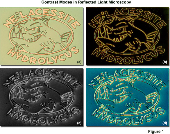
In its standard configuration, a typical reflected light microscope is readily equipped to examine amplitude (absorption) specimens using brightfield incident light. Natural absorption specimens are distinguished from phase specimens that are converted into absorption specimens by chemical treatment, such as etching and polishing the specimen, or coating the surface with a transparent, thin highly refractive layer. Presented in Figure 1 are reflected light digital images revealing details in a tiny feature intentionally placed on the surface of a computer chip using evaporated metal during the fabrication phase. Figure 1(a) shows the feature in brightfield, while Figures 1(b), 1(c), and 1(d) show the same viewfield in darkfield, polarized light, and differential interference contrast (DIC), respectively. Note the significant differences in contrast that can be obtained using these techniques.
Chemical etching is one of the most popular methods for introducing contrast into metallic specimens. In reflected light microscopy using brightfield illumination, etched structures of the polished specimen become visible due to shadow effects produced by a variety of mechanisms, such as the formation of reliefs, reflections due to cover layers, or reflectance effects arising from etch pits. Careful attention to detail in specimen preparation is important in order to avoid artifacts or misinterpretation of the acquired data. In most cases, a freshly prepared, correctly ground and polished specimen is necessary in order to observe and record important features of interest. Etching can be performed with chemical agents, electrolytic etching (specimen acts as an anode or cathode when bathed in an electrolyte), thermal etching in normal atmosphere or in a vacuum or inert gas. A note of caution should be applied to chemical etching. The process often damages structural elements of the polished specimen where small crystallites are lost. In these cases, the specimen can display only the crystal boundaries, which are not differentiated according to phase changes.
Specimen damage and loss of phase differentiation can be avoided by applying evaporated interference layers to the specimen. This purely physical technique uses a transparent, thin refractive substance (such as titanium dioxide, zinc selenide, or zinc telluride) compatible with the specimen phases, which can be evaporated onto the polished surface. Multiple reflections and interference effects generated by the evaporated film increase contrast so that the specimen can be examined in brightfield reflected light. Among the important parameters to consider when coating specimens is the refractive index of the specimen phase, the refractive index and thickness of the evaporated film, and the wavelength of light used for imaging. In many cases, monochromatic illumination is preferable to broadband white light. An interference filter can be inserted into the vertical illuminator to achieve illumination with a specific color or band of wavelengths.
Contrast can be enhanced in single phases, for example on a polished metal surface, using a gas-ion reaction chamber. The technique employs a residual gas ionized by electron irradiation so that the specimen surface is subjected to the gas in a vacuum chamber. When oxygen is used as the residual gas, the different specimen phases form oxide layers that give rise to colors due to absorption and interference when examined in brightfield reflected light. The degree of contrast enhancement is influenced by the type of residual gas, vacuum pressure, the density of the electron current emitted by the cathode, the discharge voltage, and the temperature of the specimen surface. Contamination can be avoided by heating the specimen, reducing current density, and using oxygen ions in the chamber. This technique can also be applied to non-metallic specimens for general material contrasting. In general, etched and coated specimens can be observed using standard long-working distance reflected light objectives.
back to top ^Darkfield Reflected Light Microscopy
Darkfield reflected light illumination is especially useful for revealing fissures, pores, and grain boundaries in semi-opaque specimens. Oxidation products often feature characteristic intrinsic colors, and the quality of a polished specimen can be gauged using darkfield illumination. On a dark background, polishing scratches appear as bright lines. In darkfield illumination, only the wavefronts arising to stray reflection by structural elements in the specimen are able to enter the objective. Those wavefronts reflected by surface elements positioned perpendicular to the microscope optical axis do not reach the objective and these areas remain dark. The instrument configuration features an opaque occluding disk that is placed into the light path in the vertical illuminator so that only the peripheral wavefronts reach the deflecting mirror above the objective. Waves reflected by the mirror pass through a hollow collar surrounding the objective and serve to illuminate the specimen (see Figure 2) at highly oblique angles.
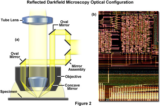
The darkfield reflected light microscope contains a standard vertical illuminator where the light is deflected downwards toward the objective via a mirror step assembly and another mirror containing an oval opening (see Figure 2). After the reflected wavefronts pass through a sleeve inside the objective decorative barrel, they impact a ring-shaped concave mirror that directs them toward the specimen surface at a high angle of incidence. The optical elements of the objective do not contribute to specimen illumination. In addition, only those wavefronts diffusely reflected by the specimen surface reach the objective front lens element and contribute more or less strongly to contrast in the darkfield image. The highest degree of contrast is obtained when the background is black and the structural features (such as grain boundaries) are observed as bright entities. Note that in darkfield reflected light microscopy, the field and aperture diaphragms in the vertical illuminator should be opened to their widest points so that the light beam illuminating the mirror assembly is not partially blocked. The image in Figure 2(b) is a darkfield reflected light view of the surface of a microprocessor computer chip.
Modern reflected light microscopes equipped with accessories for darkfield illumination offer a wide spectrum of innovations. Among these are erect image capability that produces non-reversed letters (especially important in semiconductor technology) when photographed or imaged digitally. Additional critical features present on the specimen surface are also positioned in the correct orientation in images using the erect image technique. The move to infinity-corrected optical systems by most manufactures helps to eliminate ghost images and astigmatism often generated by the use of half-mirrors, especially when auxiliary components are added to the optical path. Infinity-corrected brightfield and darkfield objectives offered by some manufacturers offer an increased effective field of view and a wide range of working distances for enhanced optical performance, especially when coupled to ultra-wide viewfield eyepieces. Advanced new illumination systems provide quick and easy changeover between tungsten-halogen and high-energy mercury or xenon light sources to provide optimum illumination for faint darkfield specimens. Also, some reflected light microscopes have internal optical elements that provide built-in zoom magnification to assist focusing and enable intermediate (although sometimes empty) magnifications.
Recent advances in reflected light microscopy have been largely driven by the semiconductor industry, materials sciences, and explosive growth in fluorescence microscopy for medical diagnostics and cell sciences. The ability of darkfield illumination to reveal outlines, edges, boundaries, scratches, pinholes and refractive index gradients provides a means to complement other forms of microscopy including brightfield, differential interference contrast, Hoffman modulation contrast, and polarized light techniques. When coupled together, these contrast-enhancing techniques can often lead to new insight about specific details of specimens under study.
back to top ^Polarized Reflected Light Microscopy
Polarized reflected light microscopy (Figure 3) is a technique that is suitable for examining surfaces containing structures that alter the state of polarization during the reflection process. For example, structural grains in ore samples and a number of metallic alloys and thin films can be readily examined using this method. In the optical configuration outlined in Figure 3, the illuminating wavefronts encounter a polarizer that is placed in the vertical illuminator before the mirror unit that directs light into the objective. The linearly polarized light waves are focused onto the specimen surface and reflected back into the objective. After leaving the objective aperture as a parallel bundle of wavefronts, the light is then projected onto a second polarizer (the analyzer) oriented at 90 degrees with respect to the polarizer. Only depolarized or shifted wavefronts are able to pass through the analyzer to reach the tube lens. An auxiliary lambda plate can also be inserted just prior to the analyzer in the optical train to determine the sign of birefringence or to add color (changing gray to color contrast). In cases where objectives of very low magnification are used in reflected polarized light, a rotatable optical plate (termed an Antiflex cap) consisting of a one-quarter wavelength lambda plate is placed on the objective front lens element to block reflections from the objective itself.
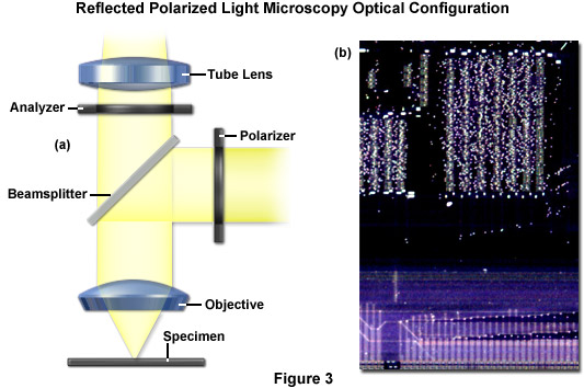
Anisotropic specimens, which are excellent candidates for polarized light microscopy, will appear dark if the primary reflections are oriented parallel to the transmission azimuths of the polarizer or analyzer. At a diagonal position (45 degrees with respect to the polarizer axis), each incident wavefront is split into two reflection components that form an elliptical wavefront upon being reflected by a birefringent surface (due to different refractive indices or absorption variations). If these reflected components are able to produce interference at the analyzer, the resulting image appears bright and perhaps colored. The analyzer can be removed to examine grains having differing orientation using a method termed reflection pleochroism. Contrast in polarized light microscopy is generated by anisotropic specimen features, magneto-optical effects, deep etching, or birefringent coatings. The image in Figure 3(b) is the same computer chip viewfield as Figure 2(b), except the illumination scheme was reflected polarized light rather than darkfield.
Careful specimen preparation is essential for success in polarized reflected light microscopy. In geological applications, the standard thickness for rock thin sections is 25 to 30 micrometers. Specimens can be ground down with diamond-permeated wheels and then hand finished to the correct thickness using abrasive powders of successively decreasing grit size. The final specimen should have a cover glass cemented with an optically transparent adhesive. Softer materials can be prepared in a method similar to biological samples using a microtome. Polarized light microscopy provides a vast amount of information about the composition and three-dimensional structure of a range of samples. Practically unlimited in its scope, the technique can reveal information about thermal history and the stress to which a specimen was subjected during formation. Useful in manufacturing and research, polarizing microscopy is a relatively inexpensive and accessible investigative and quality control tool that can provide information unavailable with any other technique.
back to top ^Differential Interference Contrast (DIC) Reflected Light Microscopy
One of the most powerful techniques for introducing contrast into reflected light imaging is differential interference contrast, which allows the visualization of minute elevation differences in surfaces. In the optical configuration (Figure 4), a birefringent prism (also known as a Wollaston or Nomarski prism, depending upon design) is placed in the infinity space just above the objective and a polarizer is installed in the vertical illuminator (similar to polarized light). The prism splits the polarized light wavefronts into two orthogonal polarized beams, oriented at 45 degrees in reference to the polarizer, on their way to the specimen. These perpendicular light beams impact the specimen to create a lateral displacement in regions where surface relief exists. If the surface is completely flat, no features are observed. However, if there is, for example, a small step between the two wavefronts (see Figure 4), one of the beams must travel a path that is longer and is assigned this path difference. Once the parallel beams have returned to the microscope after passing back through the objective and prism, they pass through a second polarizer (the analyzer) where interference produces an intermediate image where path differences are translated into gray values that can be seen by the eye. Similar to polarized light microscopy, a lambda plate can be positioned beneath the analyzer to shift gray values into colored hues.
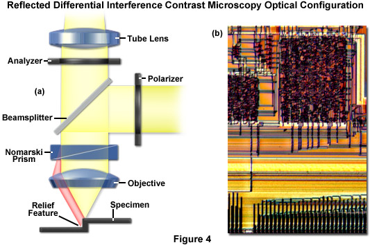
The optical components necessary for differential interference contrast observation do not mask or otherwise obstruct the objective aperture, thus enabling the instrument to be used at full numerical aperture. This results in a dramatic improvement in resolution. In addition, differential interference contrast produces an image that can be easily manipulated using digital and video imaging techniques to further enhance contrast. One of the most important considerations in many laboratories, when comparing DIC and polarized light or darkfield illumination, is the cost of accessory components. Because DIC requires several expensive birefringent Nomarski prisms and strain-free optical elements (primarily the objectives), the instrumentation is significantly more costly than most other contrast-enhancing techniques. In many cases, mainly when photomicrography and/or digital imaging are not principal considerations, darkfield illumination will often serve the purposes of a laboratory examining metallography specimens. However, when high-resolution images must be obtained in transparent phase specimens, differential interference contrast is the optimum choice technique. The image in Figure 4(b) is the same computer chip viewfield as Figure 2(b) and Figure 3(b), except the illumination scheme was reflected differential interference contrast rather than darkfield or polarized light.
Modern microscopists and optical engineers have developed a wide spectrum of useful techniques designed to aid in contrast enhancement, provide better observation, and assist in the collection of photomicrographs and digital images of a wide variety of specimens. Darkfield microscopy can be used to increase the visibility of specimens lacking in sufficient contrast that are difficult to observe with standard brightfield microscopy, while DIC is an excellent mechanism for rendering contrast in transparent specimens. The polarized light microscope, however, is designed to observe and photograph specimens that are visible primarily due to their optically anisotropic character, thus improving the quality of the image obtained with birefringent materials when compared to other techniques such as darkfield, brightfield, and differential interference contrast.
Contributing Authors
Rudi Rottenfusser - Zeiss Microscopy Consultant, 46 Landfall, Falmouth, Massachusetts, 02540.
Erin E. Wilson and Michael W. Davidson - National High Magnetic Field Laboratory, 1800 East Paul Dirac Dr., The Florida State University, Tallahassee, Florida, 32310.