


Introduction
Microscopes are specialized optical instruments designed to produce magnified visual or photographic (including digital) images of objects or specimens that are too small to be seen with the naked eye. Collectively, this varied group of tools includes not only multiple-lens (compound microscope) designs featuring objectives and condensers, but also consists of very simple single-lens instruments that are often hand-held, such as a photography loupe or common magnifying glass. Utilizing a microscope is a proficiency that can be readily learned by almost anyone. Even though at first the complex array of switches, filters, knobs, sliders, eyepiece inscriptions, and color rings on the objective may be confusing, they are readily deciphered in a short period of time. The methods of operation are based on conventions that seldom change, so once a novice has begun to understand and apply the basic principles of the technique, success is almost certainly within reach. Many years of practice, improvement, and asserting individual creative changes to the standard methodology can ultimately transform the beginner into a master microscopist.
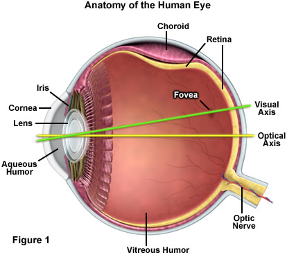
Due to the fact that a large number of microscope users rely upon direct observation of the specimen, it is critically important to understand the relationship between the microscope and the human eye. Regardless of technical advancement, the human eye as a visual detector (in combination with the brain) is the most efficient image-processing system that has ever been encountered. There are no man-made devices that can match the abilities of the human eye in regards to imaging speed and resolution. The principles of operation underlying modern cameras, however, are strongly related to the structure and operation of the eye (see the anatomical description in Figure 1). Together with the muscle-adjusted lens, the curved surface of the cornea projects an optical image onto the retina (the detector). The level of incident brightness is controlled via the variable diameter of an iris (much like an optical diaphragm) under the control of specific muscles. A sharp image is produced by the flexible lens, the focal length of which is changed by another set of muscles so that focusing is possible on any object at a distance between approximately 20 centimeters and infinity. The image itself is detected on the retina by approximately 130 million photoreceptor rod cells (responsible for recognition of grey levels) and 7 million photoreceptor cone cells (color recognition), and is then transferred to the brain along the shortest possible path through the optic nerve.
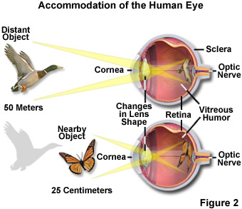
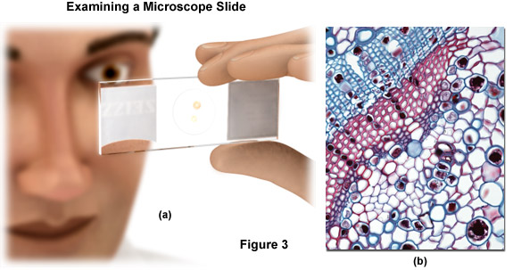
The light rays illustrated in Figure 2 form a viewing angle of 30 degrees to demonstrate accommodation of the human eye for viewing objects at varying distances. In this case, a flying duck is observed at a distance of 50 meters whereas a nearby butterfly is viewed at a much closer distance of 25 centimeters. Objects in extreme proximity to the eye cannot have their images brought into focus on the retina because of the limited ability of the eye's lens to change its shape. Furthermore, it is not practical to get any closer than approximately 10 centimeters an object being viewed due to the fact that the viewing angle becomes extremely small, which is why many details are unrecognizable. For example, if you wanted to have a closer look at the fine capillaries residing in the stalk of a plant (see Figure 3), you would cut a wafer-thin slice from the stalk, place it on a microscope slide and protect it using a cover slip (as illustrated in Figure 3(a)). Even so, when you hold the finished specimen up to the light, you would discover that much detail is left to be revealed. The many intricate features you want to see have a diameter of only one hundredth or even one thousandth of a millimeter so they cannot be recognized from such a great distance because the viewing angles are too small for the details to reach different receptors on the retina. A similar situation results when we attempt to observe the duck at a distance of 200 meters. The many intricate details present in the wings and colored markings on the bird cannot be recognized from such a great distance because the viewing angles are too small. A magnified view of the plant stalk is presented in Figure 3(b) to illustrate the power of the compound microscope.
back to top ^The Concept of Magnification
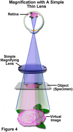
Over five hundred years ago, simple glass magnifiers were developed to assist with viewing very small objects. Such instruments consisted of one or more convex lenses (thicker in the center than the periphery) that allowed a specimen or object to be focused by the magnifier positioned between the object and the eye. Sometimes referred to as simple microscopes, they display the image on the retina by magnification through a process that increases the visual angle on the retina. Figure 4 presents an illustration of how a simple bi-convex lens operates. The image is perceived by the eye as if it were at a distance of 10 inches or 25 centimeters (the reference, or conventional viewing distance). Although the image of the specimen appears to be on the same side of the lens as the specimen itself, it cannot be projected onto a screen. Such images are termed virtual images and they appear upright, not inverted. In a compound microscope, the image appears to be floating in space just below the top of the observation tube (at the level of the fixed diaphragm of the eyepiece) where the eyepiece is inserted. What you are observing is not tangible; it cannot be grasped. Rather, it is a map or representation of the specimen in various colors and/or shades of gray from black to white.
More than an 8-fold or 10-fold magnification is not very useful with a simple bi-convex lens because of the resulting small field of view and the fact that the lens must be brought into very close proximity to the eye. In order to achieve higher magnifications we must use the compound microscope, which was originally developed by the Janssen brothers in the Netherlands and Galileo in Italy around the beginning of the 1600s. In its simplest form, the instrument is composed of two convex lenses aligned in series: An object glass (more commonly referred to as an objective) closer to the object or specimen, and an eyepiece (ocular) lens closer to the observer's eye (with means of adjusting the position of the specimen and the microscope lenses). The compound microscope achieves a two-stage magnification where the objective projects a magnified image into the body tube of the microscope and the eyepiece further magnifies the image projected. The total magnification equals the magnification of the objective multiplied by the magnification of the eyepiece:
The earliest compound microscopes were hindered by optical aberrations (both chromatic and spherical). Such defects result from the fact that white light is composed of numerous wavelengths, and when light waves pass through the periphery of a lens, they are not brought into focus with those passing through the center. The images that early microscopes produced were often blurred with colorful halos until lens makers in the mid-1700s discovered that by combining two lenses made of glass with different color dispersions, much of the chromatic aberration could be reduced or eliminated. Modern microscopes are often modular with interchangeable parts for different purposes, and can have several lenses arranged one behind the other, thus allowing magnifications of up to 2000x and higher, and the capability of producing images with remarkable clarity and contrast.
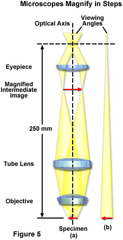
Illustrated in Figure 5 is the infinity color-corrected optical system (ICS) principle used with a modern microscope featuring a tube lens as added support for the objective. In the microscope beam path (Figure 5(a)), the object or specimen is recorded by the objective and is first projected at infinity with a parallel bundle of wavefronts or rays. In effect, the light rays originating from one point of the specimen travel in straight, parallel lines behind the objective. The tube lens then functions in a similar way to a camera to focus the parallel ray bundles, producing a magnified intermediate image located inside the eyepiece at its front focal plane. The eyepiece, acting as a second magnifier, translates the dimension of the intermediate image into parallel rays. The resulting viewing angle of the sophisticated compound microscope system is much larger than results from direct observation (Figure 5(b)), where the object is seen directly from a distance of approximately 25 centimeters. The region where these parallel bundles intersect is termed the eye point, and that is where the iris of the eye should be located. The cornea and lens of the eye focus these parallel rays onto the retina. As described above, the total magnification equals the objective magnification multiplied by the eyepiece magnification. In this illustrative example, the overall magnification of the microscope is 100x (10x objective with a 10x eyepiece).
At a selected numerical aperture (the sine of the angular aperture of the objective multiplied by the refractive index of the imaging medium) where the microscope presents a magnified image with a magnitude equivalent to the resolution limit of the human eye, further magnification beyond this point does not result in the resolution of even finer specimen detail. The range of useful total magnification for an objective and eyepiece combination is defined by the numerical aperture of the system. There is a minimum magnification necessary for the detail present in an image to be resolved by the eye, and this value is typically set at 500 times the numerical aperture (500 x NA). At the other end of the spectrum, the maximum useful magnification of an image is usually set at 1000 times the numerical aperture (1000 x NA). This limit is set by the wave nature of light imposed on the objective by diffraction. Magnifications higher than this value will yield no additional useful information of finer resolution of image detail, and will usually lead to image degradation. Exceeding the limit of useful magnification causes the image to suffer from empty magnification, where increasing magnification through the eyepiece or intermediate tube lens only causes the image to become more magnified with no corresponding increase in detail resolution.
These basic principles of magnification underlie the operation and construction of the compound microscope. The elaboration of these principles has led to the development, over the past several hundred years, of today's sophisticated instruments capable of producing high-quality images from low to high magnification.
Contributing Authors
Rudi Rottenfusser - Zeiss Microscopy Consultant, 46 Landfall, Falmouth, Massachusetts, 02540.
Erin E. Wilson and Michael W. Davidson - National High Magnetic Field Laboratory, 1800 East Paul Dirac Dr., The Florida State University, Tallahassee, Florida, 32310.