


Introduction
A transmitted light microscope will typically be of little use to anyone wanting to examine the structure of metallic samples, the surface of ceramics, integrated circuits, or printed paper documents. As a result, the reflected light microscope has been developed for these purposes. Reflected light microscopy is often referred to as incident light, epi-illumination, or metallurgical microscopy, and is the method of choice for fluorescence and for imaging specimens that remain opaque even when ground to a thickness of 30 micrometers. Much like the fluorescence microscope, in reflected brightfield microscopy the sample is illuminated from above through the objective. The Köhler illumination principle applies in cases where the objective with its pupil plane is also utilized as the condenser.
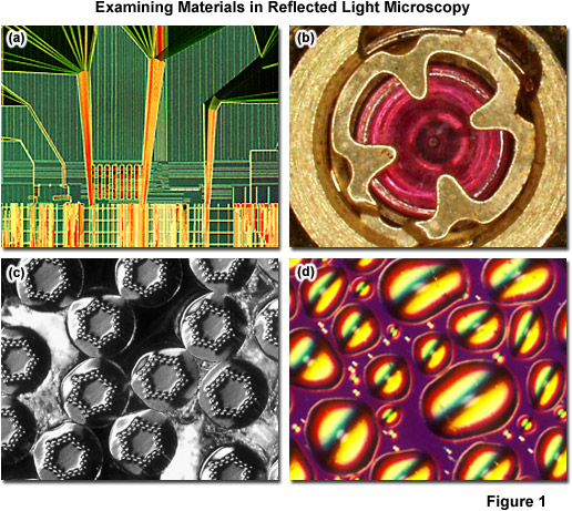
The range of specimens falling into this category is enormous and includes most metals, ores, ceramics, many polymers, semiconductors (unprocessed silicon, wafers, and integrated circuits), slag, coal, plastics, paint, paper, wood, leather, glass inclusions, and a wide variety of specialized materials. Because light is unable to pass through these specimens, it must be directed onto the surface and eventually returned to the microscope objective by either specular or diffused reflection. As mentioned above, such illumination is most often referred to as episcopic illumination, epi-illumination, or vertical illumination (essentially originating from above), in contrast to diascopic (transmitted) illumination that passes through a specimen. Several reflected light specimens are presented in Figure 1. The surface of an integrated circuit is shown using reflected light differential interference contrast (DIC) in Figure 1(a), while the jewel bearing of a watch mechanism captured in brightfield is presented in Figure 1(b). Darkfield is another useful reflected light technique, as evidenced by the image revealing surface structure of a superconducting wire cable in Figure 1(c). Finally, a magnetic thin film (Figure 1(d)) can be imaged using polarized reflected light microscopy to examine surface defects (blisters) that affect the homogeneity of the film.
back to top ^The Reflected Light Microscope
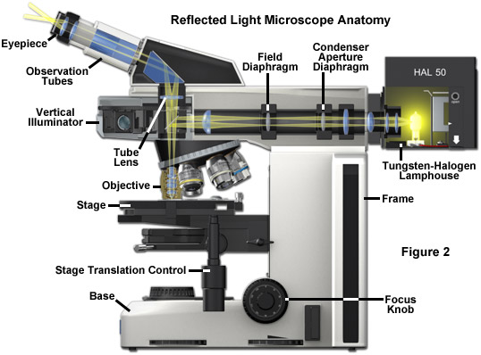
Today, many microscope manufacturers offer advanced models that permit the user to alternate or simultaneously conduct investigations using both vertical and transmitted illumination. A typical microscope configured for both types of illumination is illustrated in Figure 2 (the transmitted light source and optical pathway is not shown in this illustration). The optical pathway for reflected light begins with illuminating rays originating in the lamp housing for reflected light (the upper housing in Figure 2). This light next passes through the collector lens and into the vertical illuminator where it is controlled by the aperture and field diaphragms. After passing through the vertical illuminator, the light is then reflected by a beamsplitter (a half mirror or elliptically shaped first-surface mirror) through the objective to illuminate the specimen. Light reflected from the surface of the specimen re-enters the objective and passes into the binocular head where it is directed either to the eyepieces or to a port for photomicrography. Reflected light microscopy is frequently the domain of industrial applications, especially in the rapidly growing semiconductor arena, and thus represents a most important segment of microscopical studies.
A typical upright compound reflected light microscope has a viewing tube with two eyepieces (Figure 2) and often a trinocular tube head for mounting a conventional or digital/video camera system (not illustrated). Standard equipment eyepieces are usually of 10x magnification, and most microscopes are equipped with a nosepiece capable of holding four to six objectives. The stage is mechanically controlled with a specimen holder that can be translated in the x- and y- directions and the entire stage unit is capable of precise up and down movement with a coarse and fine focusing mechanism. Built-in light sources range from 20 and 100 watt tungsten-halogen bulbs to higher energy mercury vapor or xenon lamps that are used in fluorescence microscopy. Light passes from the lamphouse through a vertical illuminator interposed above the nosepiece but below the underside of the viewing tube head. The specimen's top surface is upright (usually without a coverslip) on the stage facing the objective, which has been rotated into the microscope's optical axis. The vertical illuminator is horizontally oriented at a 90-degree angle to the optical axis of the microscope and parallel to the table top, with the lamp housing attached to the back of the illuminator. The coarse and fine adjustment knobs raise or lower the stage in large or small increments to bring the specimen into sharp focus.
Inverted reflected light microscope stands incorporate the vertical illuminator within the body of the microscope. Many types of objectives can be used with inverted reflected light microscopes, and all modes of reflected light illumination may be possible: brightfield, darkfield, polarized light, differential interference contrast, and fluorescence. Some of the instruments include a magnification changer for zooming in on the image, contrast filters, and a variety of reticules. Because an inverted microscope is a favorite instrument for metallographers, it is often referred to as a metallograph. Manufacturers are largely migrating to using infinity-corrected optics in reflected light microscopes, but there are still thousands of fixed tube length microscopes in use with objectives corrected for a tube length between 160 and 210 millimeters.
On the inverted stand (similar in basic construction to the inverted tissue culture style microscope frames commonly employed in biology), the specimen is placed on the stage with its surface of interest facing downward. The primary advantage of this design is that samples can be easily examined when they are far too large to fit into the confines of an upright microscope (such as large rock samples and industrial materials). Also, only the side of the specimen facing the objectives need be perfectly flat. The objectives are mounted on a nosepiece under the stage with their front lenses facing upward towards the specimen and focusing is accomplished either by moving the nosepiece or the entire stage up and down.
In the vertical illuminator, light travels from the light source, usually a 12 volt 50 or 100 watt tungsten-halogen lamp, passes through collector lenses, through the variable aperture iris diaphragm opening and through the opening of a variable and centerable pre-focused field iris diaphragm. The light then strikes a partially silvered plane glass reflector, or strikes a fully silvered periphery of a mirror with elliptical opening for darkfield illumination. The plane glass reflector is partially silvered on the glass side facing the light source and anti-reflection coated on the glass side facing the observation tube in brightfield reflected illumination. Light is thus deflected downward into the objective. The mirrors are tilted at an angle of 45 degrees to the path of the light travelling along the vertical illuminator.
In reflected light microscopy, absorption and diffraction of the incident light rays by the specimen often lead to readily discernible variations in the image, from black through various shades of gray, or color if the specimen is colored. Such specimens are known as amplitude specimens and may not require special contrast methods or treatment to make their details visible. Other specimens show so little difference in intensity and/or color that their feature details are extremely difficult to discern and distinguish in brightfield reflected light microscopy. The latter specimens behave much like the phase specimens so familiar in transmitted light work, and are suited for darkfield and reflected light differential interference contrast applications.
back to top ^Objectives for Reflected Light Microscopy
The resolving power in reflected light is based on the same relationship between the wavelength of light and numerical aperture (the Abbe equation) as in transmitted light. Optical performance is achieved in reflected light illumination when the instrument is adjusted to operate under Köhler illumination. A function of Köhler illumination (aside from providing evenly dispersed illumination) is to ensure that the objective will be able to deliver excellent resolution and good contrast even if the source of light is a coiled filament lamp. In many cases, modern reflected light microscopes may also be operated using transmitted light because the parfocal length is maintained in all objectives.
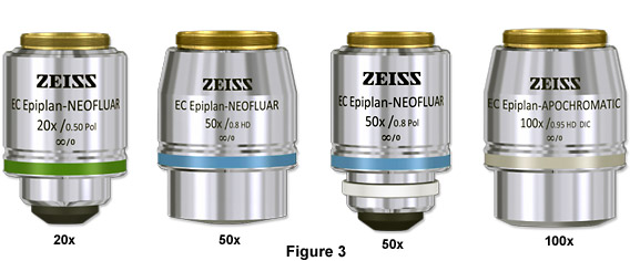
Objectives for reflected light can be recognized by the Epi or similar inscription on the decorative outer barrel (see Figure 3). They differ from objectives for transmitted light in two ways. Reflected light objectives feature lens surfaces that are particularly well coated with anti-reflection layers to prevent the illuminator light from being reflected towards the eyepiece. Such reflections would be superimposed on the image and have a disturbing effect. The second difference is that these objectives are designed and optically corrected for specimens lacking a coverslip. The vast majority of samples in the materials sciences (where reflected light microscopes are most heavily used) are usually viewed without a cover slip. Therefore, higher numerical aperture objectives require a different optical computation than do transmitted light objectives.
back to top ^Reflected Light Microscope Illuminators
In reflected light microscopy, illuminating light reaches the specimen, which may absorb some of the light and reflect some of the light, either in a specular or diffuse manner. Light that is returned upward can be captured by the objective in accordance with the objective's numerical aperture. After entering the objective, light then passes through the partially silvered mirror (or in darkfield, through the elliptical opening). In the case of infinity-corrected objectives, the light emerges from the objective in parallel (from every azimuth) wavefronts projecting an image of the specimen to infinity. The parallel rays enter the tube lens, which forms the specimen image at the plane of the fixed diaphragm opening in the eyepiece (intermediate image plane). It is important to note, that in these reflected light systems, the objective serves a dual function. For light waves on the way down to the specimen, the objective serves as a matching well-corrected (always properly aligned) condenser. Alternatively, for waves reflected by the specimen, the objective serves as an image-forming optical system in the customary role of an objective projecting the image-carrying rays toward the eyepiece. Optimal performance is achieved in reflected light illumination when the instrument is adjusted to produce Köhler illumination (discussed below). A function of Köhler illumination (aside from providing evenly dispersed illumination) is to ensure that the objective will be able to deliver excellent resolution and good contrast even if the source of light is a coiled filament lamp.
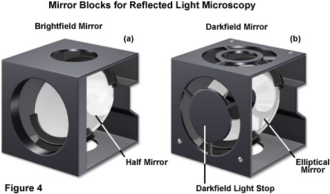
Several modern reflected light illuminators are described as universal illuminators because, with several additional accessories and little or no dismantling, the microscope can easily be switched from one mode of reflected light microscopy to another. Often, reflectors can be removed from the light path altogether in order to permit transmitted light observation. Universal illuminators may include a partially reflecting plane glass surface (the half-mirror) for brightfield (see Figure 4(a)), and a fully silvered reflecting surface with an elliptical, centrally located clear opening for darkfield observation (Figure 4(b)). The best-designed vertical illuminators include collector lenses to gather and control the light, an aperture iris diaphragm and a pre-focused, centerable field diaphragm to permit the desirable Köhler illumination.
The vertical illuminator should also make provision for the insertion of filters for contrast, digital imaging, and photomicrography, as well as polarizers, analyzers, and compensator plates for polarized light and differential interference contrast (DIC) illumination. In vertical illuminators designed for use with infinity-corrected objectives, the illuminator may also include a tube lens. Affixed to the back end of the vertical illuminator is a lamphouse (Figure 2), which usually contains a tungsten-halogen lamp. For fluorescence work, the lamphouse can be replaced with a fitting containing a mercury burner. The lamp may be powered by the electronics built into the microscope stand, or in fluorescence, by means of an external transformer or power supply.
back to top ^Köhler Illumination in Reflected Light Microscopy
In a reflected light microscope vertical illuminator, the light source is positioned so that the tungsten-halogen lamp filament is located near the principal focal point of the collector lens. In Köhler illumination, the lamp collector lens serves the function of a dramatically enlarged secondary light source to enhance overall illumination. One of the primary requirements of Köhler illumination is that an image of the lamp filament must ultimately be projected onto the rear focal plane of the objective, which also doubles as the (often high numerical aperture) condenser during excitation in reflected light illumination. The light source should ideally fill the entire objective aperture to both maximize the intensity of radiation and to produce an evenly illuminated field. In many cases, a ground glass filter is placed into the vertical illuminator between the lamphouse and the neutral density filters in order to increase the uniformity of illumination. However, because diffusion filters also reduce the level of illumination, they should be avoided whenever possible.
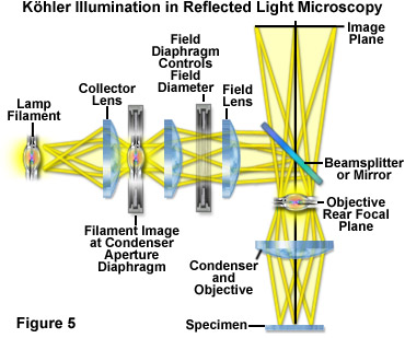
In reflected light Köhler illumination (illustrated schematically in Figure 5), an image of the light source is focused by the collector lens onto the aperture iris diaphragm located in the vertical illuminator. This diaphragm shares a conjugate plane with the rear aperture of the objective and the lamp filament, and therefore, determines the illuminated field aperture size. Together, the light source, vertical illuminator aperture diaphragm, and objective rear focal plane (pupil) form the illumination set of conjugate planes. Unlike the situation in transmitted light microscopy, the aperture iris and light source are imaged onto the objective (acting as a condenser) rear aperture plane, rather than being physically located at this position. As an added benefit to this configuration, all obstructions (such as iris diaphragms) are removed from the light path. Opening or closing the aperture diaphragm is used to control stray light and regulate the intensity (numerical aperture) of illumination without altering the size of the illuminated field. In the image, adjustment of the aperture diaphragm affects brightness and contrast.
The image-forming or field set of conjugate planes in reflected light Köhler illumination consists of the field diaphragm, the specimen surface, and the intermediate image plane. Thus, when the field diaphragm is placed in focus at the specimen plane, the image of the light source is significantly removed from focus in order to provide a uniform field of illumination. The field diaphragm controls the size of the illuminated field without affecting the illumination intensity of the area being observed. In practice, the field diaphragm opening size should be as small as possible in order to increase image contrast. Köhler illumination produces even illumination of the specimen field in spite of the uneven illumination intensity generated by most filament-based light sources. When the microscope is properly configured, the rear focal plane of the objective is fully illuminated, providing a field that is uniformly bright from edge to edge. Köhler illumination, in the ideal case, bathes the specimen with a converging set of wavefronts, each arising from separate points on the light source imaged into the condenser aperture. In a properly configured reflected light microscope, the result is optimum image contrast and resolution.
back to top ^Brief Overview Contrast Modes in Reflected Light Microscopy
Due to the fact that the objective serves a dual purpose (also performing as a condenser) in reflected light microscopy (refer to Figure 6(a)), there is sufficient room to introduce auxiliary components into the infinity space occupied by the parallel bundle of light wavefronts traveling from the objective rear aperture to the tube lens (termed the observation side of the optical train; see Figure 6(a)). In addition, polarizing or filter components can be inserted into the vertical illuminator before light enters the objective (termed the optical train illumination side). Many modern microscopes also provide additional space for components that affect both light paths. This space is usually built as a slot in the objective nosepiece where a slider containing either a filter or polarizer can be easily inserted.
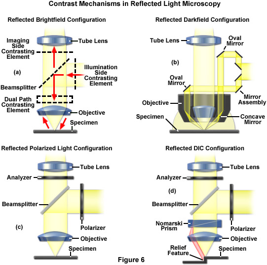
Several techniques are commonly employed to introduce contrast in reflected light microscopy, including darkfield illumination, polarized light, and differential interference contrast. In reflected darkfield microscopy, which is an ideal methodology for exploring the relief in surfaces of materials, wavefronts from the vertical illuminator are directed toward the objective using a specialized mirror assembly that contains an oval opening (see Figure 4 and Figure 6(b)). This light passes through an outer sleeve in the microscope objective and impacts on a ring-shaped concave mirror, which directs the wavefronts at a highly incident angle onto the specimen surface. In cases where the specimen acts as a perfect mirror (in effect, there are no relief features on the surface), there is no light reflected back into the objective from the specimen and the image remains dark. Areas where relief contours exist, however, direct light back into the objective front lens and are observed as being bright features against a very dark background. Note that in darkfield reflected light microscopy, the field and aperture diaphragms in the vertical illuminator should be opened to their widest points so that the light beam illuminating the mirror assembly is not partially blocked.
Polarized reflected light microscopy (Figure 6(c)) is a technique that is suitable for examining surfaces containing structures that alter the state of polarization during the reflection process. For example, structural grains in ore samples and a number of metallic alloys and thin films can be readily examined using this method. In the optical configuration outlined in Figure 6(c), the illuminating wavefronts encounter a polarizer that is placed in the vertical illuminator before the mirror unit that directs light into the objective. The linearly polarized light waves are focused onto the specimen surface and reflected back into the objective. After leaving the objective aperture as a parallel bundle of wavefronts, the light is then projected onto a second polarizer (the analyzer) oriented at 90 degrees with respect to the polarizer. Only the depolarized wavefronts are able to pass through the analyzer to reach the tube lens. An auxiliary lambda plate can also be inserted just prior to the analyzer in the optical train to examine the sign of birefringence (changing gray to color contrast). This method is sometimes referred to as sensitive tint. In cases where objectives of very low magnification are used in reflected polarized light, a rotatable optical plate (termed an Antiflex cap) consisting of a one-quarter wavelength lambda plate is placed on the objective front lens element to block reflections from the objective itself. The Antiflex method is also particularly useful when the specimen has very low reflectivity, such as would be observed in coal samples.
One of the most powerful techniques for introducing contrast into reflected light imaging is differential interference contrast, which allows the visualization of minute elevation differences in surfaces. In the optical configuration (Figure 6(d)), a birefringent prism (also known as a Wollaston or Nomarski prism, depending upon design) is placed in the infinity space just above the objective and a polarizer is installed in the vertical illuminator (similar to polarized light). The prism splits the polarized light wavefronts into two orthogonal polarized beams on their way to the specimen. These perpendicular light beams impact the specimen to create a lateral displacement in regions where surface relief exists. If the surface is completely flat, no features are observed. However, if there is, for example, a small step (see Figure 6(d)) between the two wavefronts, one of the beams must travel a path that is longer and is assigned this path difference. Once the parallel beams have returned to the microscope after passing back through the objective and prism, they pass through a second polarizer (the analyzer) where interference produces an intermediate image where path differences are translated into gray values that can be seen by the eye. Similar to polarized light microscopy, a lambda plate can be positioned beneath the analyzer to shift gray values into colored hues.
Contributing Authors
Rudi Rottenfusser - Zeiss Microscopy Consultant, 46 Landfall, Falmouth, Massachusetts, 02540.
Erin E. Wilson and Michael W. Davidson - National High Magnetic Field Laboratory, 1800 East Paul Dirac Dr., The Florida State University, Tallahassee, Florida, 32310.