


Introduction
The numerical aperture of a microscope objective is the measure of its ability to gather light and to resolve fine specimen detail while working at a fixed object (or specimen) distance. Image-forming light waves pass through the specimen and enter the objective in an inverted cone as illustrated in Figure 1(a). White light consists of a wide spectrum of electromagnetic waves, the period lengths of which range between 400 and 700 nanometers. As a reference, it is important to know that 1 millimeter equals 1000 micrometers and 1 micrometer equals 1000 nanometers. Light of green color has a wavelength range centered at 550 nanometers, which corresponds to 0.55 micrometers. If small objects (such as a typical stained specimen mounted on a microscope slide) are viewed through the microscope, the light incident on these minute objects is diffracted so that it deviates from the original direction (Figure 1(a)). The smaller the object, the more pronounced the diffraction of incident light rays will be. Higher values of numerical aperture permit increasingly oblique rays to enter the objective front lens, which produces a more highly resolved image and allows smaller structures to be visualized with higher clarity. Illustrated in Figure 1(a) is a simple microscope system consisting of an objective and specimen being illuminated by a collimated light beam, which would be the case if no condenser was used. Light diffracted by the specimen is presented as an inverted cone of half-angle (α), which represents the limits of light that can enter the objective. In order to increase the effective aperture and resolving power of the microscope, a condenser (Figure 1(b)) is added to generate a ray cone on the illumination side of the specimen. This enables the objective to gather light rays that are the result of larger diffraction angles, increasing the resolution of the microscope system. The sum of the aperture angles of the objective and the condenser is referred to as the working aperture. If the condenser aperture angle matches the objective, maximum resolution is obtained.
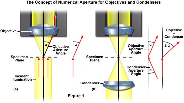
In order to enable two objectives to be compared and to obtain a quantitative handle on resolution, the numerical aperture, or the measure of the solid angle covered by an objective is defined as:
Numerical Aperture (NA) = η sin(α)(1)
where α equals one-half of the objective's opening angle and η is the refractive index of the immersion medium used between the objective and the cover slip protecting the specimen (η = 1 for air; η = 1.51 for oil or glass). By examining Equation (1), it is apparent that the refractive index is the limiting factor in achieving numerical apertures greater than 1.0. Therefore, in order to obtain higher working numerical apertures, the refractive index of the medium between the front lens of the objective and the specimen cover slip must be increased. The highest angular aperture obtainable with a standard microscope objective would theoretically be 180 degrees, resulting in a value of 90 degrees for the half-angle used in the numerical aperture equation. The sine of 90 degrees is equal to one, which suggests that numerical aperture is limited not only by the angular aperture, but also by the imaging medium refractive index. Practically, aperture angles exceeding 70 to 80 degrees are found only in the highest-performance objectives that typically cost thousands of dollars.
The resolution of an optical microscope is defined as the smallest distance between two points on a specimen that can still be distinguished as two separate entities. Resolution is directly related to the useful magnification of the microscope and the perception limit of specimen detail, though it is a somewhat subjective value in microscopy because at high magnification, an image may appear out of focus but still be resolved to the maximum ability of the objective and assisting optical components. Due to the wave nature of light and the diffraction associated with these phenomena, the resolution of a microscope objective is determined by the angle of light waves that are able to enter the front lens and the instrument is therefore said to be diffraction limited. This limit is purely theoretical, but even a theoretically ideal objective without any imaging errors has a finite resolution.
Observers will miss fine nuances in the image if the objective projects details onto the intermediate image plane that are smaller than the resolving power of the human eye (a situation that is typical at low magnifications and high numerical apertures). The phenomenon of empty magnification will occur if an image is enlarged beyond the physical resolving power of the images. For these reasons, the useful magnification to the observer should be optimally above 500 times the numerical aperture of the objective, but not higher than 1,000 times the numerical aperture.
back to top ^Immersion Media
One way of increasing the optical resolving power of the microscope is to use immersion liquids between the front lens of the objective and the cover slip. Most objectives in the magnification range between 60x and 100x (and higher) are designed for use with immersion oil. Good results have been obtained with oil that has a refractive index of n = 1.51, which has been precisely matched to the refractive index of glass. All reflections on the path from the object to the objective are eliminated in this way. If this trick were not used, reflection would always cause a loss of light in the cover slip or on the front lens in the case of large angles (Figure 2).
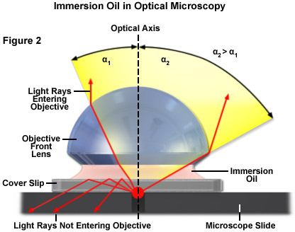
The useful numerical aperture of the objective and therefore the resolving power would be reduced by the reflection described above. The numerical aperture of an objective is also dependent, to a certain degree, upon the amount of correction for optical aberration. Highly corrected objectives tend to have much larger numerical apertures for the respective magnification as illustrated in Table 1.
Objective Numerical Aperture versus Optical Correction
|
||||||||||||||||||||||||||||||||||||||||||||||||||
Table 1
back to top ^The Airy Disk and Microscope Resolution
When light from the various points of a specimen passes through the objective and is reconstituted as an image, the various points of the specimen appear in the image as small patterns (not points) known as Airy patterns. This phenomenon is caused by diffraction or scattering of the light as it passes through the minute parts and spaces in the specimen and the circular rear aperture of the objective. The limit up to which two small objects are still seen as separate entities is used as a measure of the resolving power of a microscope. The distance where this limit is reached is known as the effective resolution of the microscope and is denoted as d0. The resolution is a value that can be derived theoretically given the optical parameters of the instrument and the average wavelength of illumination.
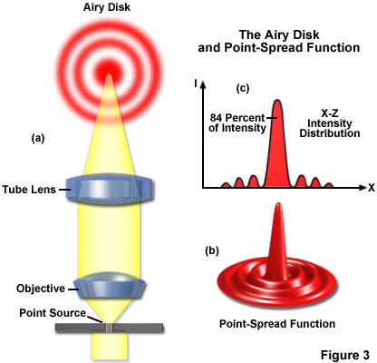
It is important, first of all, to know that the objective and tube lens do not image a point in the object (for example, a minute hole in a metal foil) as a bright disk with sharply defined edges, but as a slightly blurred spot surrounded by diffraction rings, called Airy disks (see Figure 3(a)). Three-dimensional representations of the diffraction pattern near the intermediate image plane are known as the point-spread function (Figure 3(b)). An Airy disk is the region enclosed by the first minimum of the airy pattern and contains approximately 84 percent of the luminous energy, as depicted in Figure 3(c). The point-spread function is a three-dimensional representation of the Airy disk.
Resolution can be calculated according to the famous formula introduced by Ernst Abbe in the late 19th Century, and represents a measure of the image sharpness of a light microscope:
Resolutionx,y = λ / 2[η • sin(α)](2) Resolutionz = 2λ / [η • sin(α)]2(3)
where λ is the wavelength of light, η represents the refractive index of the imaging medium as described above, and the combined term η • sin(α) is known as the objective numerical aperture (NA). Objectives commonly used in microscopy have a numerical aperture that is less than 1.5, restricting the term α in Equations (2) and (3) to less than 70 degrees (although new high-performance objectives closely approach this limit). Therefore, the theoretical resolution limit at the shortest practical wavelength (approximately 400 nanometers) is around 150 nanometers in the lateral dimension and approaching 400 nanometers in the axial dimension when using an objective having a numerical aperture of 1.40. Thus, structures that lie closer than this distance cannot be resolved in the lateral plane using a microscope. Due to the central significance of the interrelationship between the refractive index of the imaging medium and the angular aperture of the objective, Abbe introduced the concept of numerical aperture during the course of explaining microscope resolution.
The diffraction rings in the Airy disk are caused by the limiting function of the objective aperture such that the objective acts as a hole, behind which diffraction rings are found. The higher the aperture of the objective and of the condenser, the smaller d0 will be. Thus, the higher the numerical aperture of the total system, the better the resolution. One of the several equations related to the original Abbe formula that have been derived to express the relationship between numerical aperture, wavelength, and resolution is:
Resolutionx,y or d0 = 1.22λ / [NAObj + NACon](4)
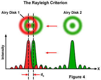
Where λ is the imaging wavelength of light, NACon is the condenser numerical aperture, and NAObj equals the objective numerical aperture. The factor 1.22 has been taken from the calculation for the case illustrated in Figure 4 for the close approach of two Airy disks where the intensity profiles have been superimposed. If the two image points are far away from each other, they are easy to recognize as separate objects. However, when the distance between the Airy disks is increasingly reduced, a limit point is reached when the principal maximum of the second Airy disk coincides with the first minimum of the first Airy disk. The superimposed profiles display two brightness maxima that are separated by a valley. The intensity in the valley is reduced by approximately 20 percent compared with the two maxima. This is just sufficient for the human eye to see two separate points, a limit that is referred to as the Rayleigh criterion.
A comparison may help to make this easier to understand. It is most unlikely that a telephone cable would be used for the electronic transfer of the delicate sound of a violin, since the bandwidth of this medium is very restricted. Much better results are obtained if high-quality microphones and amplifiers are used, the frequency range of which is identical to the human range of hearing. In music, information is contained in the medium sound frequencies; however, the fine nuances of sound are contained in the high overtones. In the microscope, the subtleties of a structure are coded into the diffracted light. If you want to see them in the imaging space behind the objective, you must make sure that they are first gathered by the objective. This becomes easier with a higher aperture angle and thus an increased numerical aperture.
The numerical aperture of objectives increases with the magnification up to about 40x (see Tables 1 and 2), but levels off between 1.30 and 1.40 (depending upon the degree of aberration correction) for oil immersion versions. Presented in Table 2 are the calculated values for the resolution of objectives typically used in research and teaching laboratories. The point-to-point resolution at the specimen, d0, is listed in the table along with the magnified size of the image (D0) in the intermediate eyepiece plane (using green light of 550 nanometer wavelength). Also in the table, the value n represents the number of resolved pixels if they are organized in a linear array along the field diameter of 20 millimeters (20 millimeters/D0).
Resolution for Selected Objectives
|
||||||||||||||||||||||||||||||||||
Table 2
You should not try to increase the overall magnification of a microscope by using eyepieces providing a high additional magnification (for example, 16x, 20x or 25x) or other optical after-burners if the objective does not supply enough pixels at a low numerical aperture. On the other hand, you will miss subtle nuances if the objective projects very fine details onto the intermediate image, and you are using an eyepiece with a low magnification. In order to observe fine specimen detail in the optical microscope, the minute features present in the specimen must be of sufficient contrast and project an intermediate image at an angle that is somewhat larger than the angular resolving power of the human eye. As previously mentioned, the overall combined magnification (objective and eyepiece) of a microscope should be higher than 500x, but less than 1000x the objective aperture. This value is known as the range of the useful magnification.
In day-to-day routine observations, many microscopists do not attempt to achieve the highest image resolution that is possible with their equipment. The resolving power of a microscope is the most important feature of the optical system and influences the ability to distinguish between fine details of a particular specimen. The primary factor in determining resolution is the objective numerical aperture, but resolution is also dependent upon the type of specimen, coherence of illumination, degree of aberration correction, and other factors such as contrast-enhancing methodology either in the optical system of the microscope or in the specimen itself.
back to top ^Practical Hints to Increase Resolving Power
Modern microscope objectives permit the theoretical resolving power to be realized in practice provided that suitable specimens are being observed. However, there are several hints that can be followed to ensure success. These are listed below.
Are the objective and specimen clean? A fingerprint on the front lens of an air objective may be sufficient to affect the high-contrast image reproduction of a specimen as a result of unwanted scattered light. The same caveats apply to immersion objectives that are soiled with residues of resin or emulsions (such as oil and water). In these cases, careful cleaning of the objective front lens element using a soft cloth and lens cleaner or pure ethanol should alleviate problems.
Do the cover slips have the correct thickness? It is of critical importance that cover slips matched to objectives of high aperture (greater than 0.65) have the standard thickness of 170 micrometers due to the fact that cover slip thickness is taken into consideration when the objectives are designed. Therefore, if a cover slip of different thickness (less than 165 or more than 175 micrometers) is used, the quality of the optical image visibly suffers. In general, the rule of thumb for objectives having a numerical aperture of 0.7 or higher is that they can tolerate a variation of 10 micrometers, whereas lower numerical aperture objectives (0.3 to 0.7) can tolerate a higher level of deviation, usually up to 30 micrometers.
Are you using the correct immersion oil? All objectives having a numerical aperture greater than 0.95 are designed for use with immersion media (usually oil of refractive index 1.515). Immersion oil is free of polychlorinated biphenyls and exhibits hardly any autofluorescence. The image will be markedly impaired if air bubbles are introduced into the immersion layer, so oil must be carefully applied to avoid bubbles. Air bubbles can be readily visualized by removing the eyepiece and examining the objective rear focal plane through the microscope observation tubes (or using a Bertrand lens). If air bubbles are observed, the objective and specimen slide should be cleaned and the oil carefully re-applied.
Contributing Authors
Rudi Rottenfusser - Zeiss Microscopy Consultant, 46 Landfall, Falmouth, Massachusetts, 02540.
Erin E. Wilson and Michael W. Davidson - National High Magnetic Field Laboratory, 1800 East Paul Dirac Dr., The Florida State University, Tallahassee, Florida, 32310.