


Introduction
The design of an optical microscope must ensure that the light rays are organized and precisely guided through the instrument. Illumination of the specimen is the most important controllable variable in achieving high-quality images in microscopy, critical photomicrography, and digital imaging. Any lack of brightness is not a problem in simple brightfield microscopy, but if contrast-enhancing techniques, such as phase contrast, differential interference contrast, fluorescence, or polarization contrast are used, additional optical elements that consume a significant portion of the available light flow are inserted into the beam path. Such a situation leaves little light for observation, and as a result, the images assume a dark character. When properly adjusted, light from the condenser will fill the rear focal plane of the objective with image-forming light by projecting a cone of light to illuminate the field of view. The condenser aperture diaphragm is responsible for controlling the angle of the illuminating light cone and, consequently, the numerical aperture of the condenser. This concept is illustrated in Figure 1, where a series of condensers are illustrated with light cones (and numerical apertures) of decreasing size from left to right in the figure.
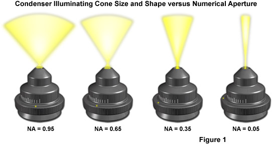
Another reason for the existence of fixed and adjustable diaphragms, prisms, beamsplitters, and filters in the microscope is that the illumination often should be reset after each change of the objective. This is, in part, because the size of the observed specimen field changes with every objective magnification. An objective with a low magnification (for example, 4x) provides a large field of observation (with a diameter as large as 5 millimeters in this case, provided that the eyepiece permits to observe an intermediate image with a diameter of 20 millimeters). If a switch is made to the 40x objective, the diameter of the viewfield of the specimen shrinks by the factor 10 (to only 0.5 millimeters). The viewable area then becomes as much as 100x smaller. The second reason is that the numerical aperture increases from 0.12 to 0.65 or, expressed as aperture angles, from 15 degrees to 80 degrees. The effect of numerical aperture on illumination light cone size and shape is presented in Figure 1.
There are a wide variety of light sources available to illuminate microscopes, both for routine observation and for quantitative digital imaging. A most common light source, because of its low cost and long life, is the 30 to 100 watt tungsten-halogen lamp. These lamps are relatively bright with a color spectrum centered at 3200 Kelvin (when set close to the nominal voltage of the lamp), but require color conversion filters to raise their color temperature to daylight equivalence. Another popular light source is the 75 to 150 watt xenon arc discharge lamp because of its very high brightness and long life. Xenon lamps feature a relatively even output of intensity across the visual spectrum, and a color temperature that approximates daylight. When very high light intensity is required, metal-halide and mercury lamps, as well as lasers are often used. In fluorescence microscopy, particularly for the purpose of digital imaging, 100 watt or 200 watt mercury burners have been used for the past several decades. These lamps are slowly yielding to the more stable and longer lived metal-halide lamps, which feature higher intensity in the continuum regions. Increasingly, light emitting diodes (LEDs) are used as a source for microscope illumination in transmitted light as well as fluorescence.
Many years ago, carbon arc lights or zirconium bulbs were used to achieve high levels of illumination, but these antique sources are seldom seen today because the lamps reduced the quality and homogeny of light reaching the sample. Köhler illumination defeats many of the limitations encountered with incandescent and arc discharge light sources by creating parallel beams that pass through the specimen in an organized manner. The Köhler strategy requires that nothing more than the viewed field of the specimen is illuminated, since the excessive light outside the field of view contains scattered light that reduces contrast. At the same time, however, one of the most critical aspects of microscopy is that the light cone of the illumination should always be matched to the angular aperture of the objective to allow the entire aperture of the optics to be effectively utilized. This is the only way to achieve maximum resolving power.
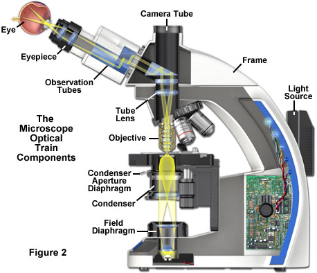
The optical train and numerous other components of a modern microscope are presented in a cut-away diagram in Figure 2. The condenser (containing the aperture diaphragm) and the luminous-field diaphragm normally contained in the stand base are the critical elements in achieving Köhler illumination. Image forming light rays passed through the specimen are captured by the microscope objective and directed either into the eyepieces and/or to one of the several camera ports. Throughout the optical train of the microscope, illumination is directed and focused through a series of diaphragms and lenses as it travels from the light source to illuminate the specimen and then into the eyepieces or camera attachment. Closing or opening the condenser diaphragm controls the angle of the light rays emerging from the condenser and reaching the specimen from all azimuths. Because the light source itself is not focused at the level of the specimen, illumination at the specimen level is essentially grainless and extended (in effect, producing a uniform field of illumination), and does not suffer deterioration from dust and imperfections on the glass surfaces of the condenser. The setting of the condenser's aperture diaphragm, along with the numerical aperture of the objective, determine the realized numerical aperture of the entire microscope system. The luminous-field diaphragm determines which portion and size of the specimen is illuminated. The aperture diaphragm of the condenser is imaged on the pupil of the objective and regulates the illumination of this pupil. The entire optical system is designed in such a manner that aperture angles of the light cones are correctly set together with the aperture diaphragm.
back to top ^Conjugate Planes in the Microscope
The microscope contains two different groups of interlaced optical planes that are responsible for controlling illumination and image formation. Collectively, these optical planes are known as conjugate planes. The first group of planes (termed the aperture planes) controls the beam path for illuminating light and produces a focused image of the lamp filament at the plane of the substage condenser aperture diaphragm, the rear focal plane of the objective, and the eye point (also called the Ramsden disk) of the eyepiece. Conjugate planes are in common focus and are critical in achieving proper Köhler illumination. A second set of planes, known as the image-forming conjugate planes include the field diaphragm, the specimen, the fixed diaphragm of the eyepiece and the retina of the eye or the surface of a camera detector. By definition, an object that is in focus at one plane is also in focus at the other conjugate planes of that light path. In each light pathway (both image-forming and illumination), there are four separate planes that together make up the conjugate plane set.
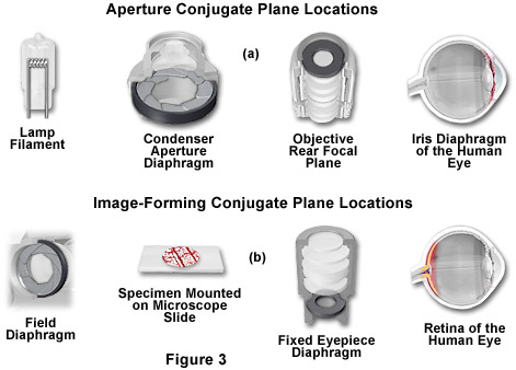
In review, conjugate planes in the path of the illuminating light rays in Köhler illumination (Figure 3(a)) include:
- The lamp filament.
- The condenser aperture diaphragm (at the front focal plane of the condenser).
- The back focal plane of the objective.
- The eye point (also called the Ramsden disk) of the eyepiece, which is located approximately one-half inch (one centimeter) above the top lens of the eyepiece, at the point where the observer places the front of the eye during observation.
Likewise, the conjugate planes in the image-forming light path in Köhler illumination (Figure 3(b)) include:
- The field diaphragm.
- The focused specimen.
- The intermediate image plane (i.e., the plane of the fixed diaphragm of the eyepiece).
- The retina of the eye, film plane, or image sensor surface of the camera.
Conjugate focal planes are often useful in troubleshooting a microscope for contaminating dust, fibers, and imperfections in the optical elements. If these artifacts are in sharp focus, it follows that they must reside on or near a surface that is part of the imaging-forming set of conjugate planes. Members of this set include the glass element at the microscope light port, the specimen, the reticle in the eyepiece, and the bottom lens element of the eyepiece. Alternatively, if these contaminants are fuzzy and out of focus, look for them near the illuminating set of elements that share conjugate planes. Suspects in this category are the condenser top lens (where dust and dirt often accumulate), the exposed eyepiece lens element (contaminants from eyelashes), and the objective front lens (usually fingerprint smudges).
It is no exaggeration to say that almost the entire art and science of microscopy (if specimen preparation is not taken into account) depends on the correct use of the luminous field and aperture diaphragms. Thankfully, there are simple rules for this. Subsequent discussions in this section describe in detail how to correctly set the microscope for Köhler illumination. The technique is recommended by all manufactures of modern laboratory microscopes because it can produce specimen illumination that is uniformly bright and free from glare, thus allowing the user to realize the microscope's full potential. It will be much easier for you if you have made yourself familiar with the relationships between the conjugate planes. The aperture planes (also known as pupils) are responsible for resolving power and contrasting techniques and can be controlled by light filters and diaphragm settings. In contrast, the field planes contain images formed by the optical components of the microscope and are the home for reticles and scales used to measure lengths. Field planes are controlled via the field diaphragm.
The field diaphragm in the base of the microscope controls only the width of the bundle of light rays reaching the condenser. This variable aperture does not affect the optical resolution, numerical aperture, or the intensity of illumination. Proper adjustment of the field diaphragm (in effect, centered in the optical path and opened so as to lie just outside of the field of view) is important for preventing glare than can reduce contrast in the observed image. The elimination of excess light is particularly important when attempting to image samples with inherently low contrast. When the field diaphragm is opened too far, scattered light originating from the specimen and light reflected at oblique angles from optical surfaces can act to degrade image quality.
The substage condenser is typically mounted directly beneath the microscope stage in a bracket that can be raised or lowered independently of the stage by rotating a knurled knob. The aperture diaphragm is opened and closed with either a swinging arm, a lever, or by rotating a collar on the condenser housing. It should be noted that correct adjustment of the substage condenser is probably the most critical aspect of achieving proper Köhler illumination. Unfortunately, however, condenser misalignment and improperly adjusted condenser aperture diaphragms are the main source of image degradation and poor quality photomicrography.
back to top ^Reflected Light Microscopy
Reflected light microscopy is often referred to as incident light, epi-illumination, or metallurgical microscopy, and is the method of choice for fluorescence and for imaging specimens that remain opaque even when ground to a thickness of 30 microns. The range of specimens falling into this category is enormous and includes most metals, ores, ceramics, many polymers, semiconductors (unprocessed silicon, wafers, and integrated circuits), slag, coal, plastics, paint, paper, wood, leather, glass inclusions, and a wide variety of specialized materials. Because light is unable to pass through these specimens, it must be directed onto the surface and eventually returned to the microscope objective by either specular or diffused reflection. As mentioned above, such illumination is most often referred to as episcopic illumination, epi-illumination, or vertical illumination (essentially originating from above), in contrast to diascopic (transmitted) illumination that passes through a specimen.
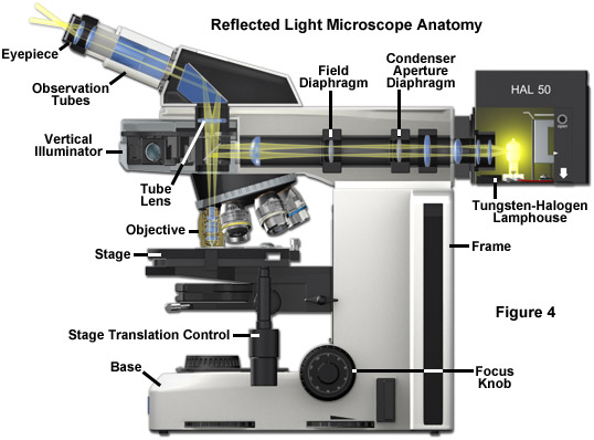
Today, many microscope manufacturers offer advanced models that permit the user to alternate or simultaneously conduct investigations using both vertical and transmitted illumination. A typical microscope configured for both types of illumination is illustrated in Figure 4 (the transmitted light source and optical pathway is not shown in this illustration). The optical pathway for reflected light begins with illuminating rays originating in the lamp housing for reflected light (the upper housing in Figure 4). This light next passes through the collector lens and into the vertical illuminator where it is controlled by the aperture and field diaphragms. After passing through the vertical illuminator, the light is then reflected by a beamsplitter (a half mirror or elliptically shaped first-surface mirror) through the objective to illuminate the specimen. Light reflected from the surface of the specimen re-enters the objective and passes into the binocular head where it is directed either to the eyepieces or to a port for photomicrography. Reflected light microscopy is frequently the domain of industrial applications, especially in the rapidly growing semiconductor arena, and thus represents a most important segment of microscopical studies.
A typical upright compound reflected light microscope has two eyepiece viewing tubes (Figure 4) and often a trinocular tube head for mounting a conventional or digital/video camera system (not illustrated). Standard equipment eyepieces are usually of 10x magnification, and most microscopes are equipped with a nosepiece capable of holding four to six objectives. The stage is mechanically controlled with a specimen holder that can be translated in the x- and y- directions and the entire stage unit is capable of precise up and down movement with a coarse and fine focusing mechanism. Built-in light sources range from 20 and 100 watt tungsten-halogen bulbs to higher energy mercury vapor or xenon lamps that are used in fluorescence microscopy. Light passes from the lamphouse through a vertical illuminator interposed above the nosepiece but below the underside of the viewing tube head. The specimen's top surface is upright (usually without a coverslip) on the stage facing the objective, which has been rotated into the microscope's optical axis. The vertical illuminator is horizontally oriented at a 90-degree angle to the optical axis of the microscope and parallel to the table top, with the lamp housing attached to the back of the illuminator. The coarse and fine adjustment knobs raise or lower the stage in large or small increments to bring the specimen into sharp focus.
Inverted microscope stands incorporate the vertical illuminator within the body of the microscope. Many types of objectives can be used with inverted reflected light microscopes, and all modes of reflected light illumination may be possible: brightfield, darkfield, polarized light, differential interference contrast, and fluorescence. Some of the instruments include a magnification changer for zooming in on the image, contrast filters, and a variety of reticles. Because an inverted microscope is a favorite instrument for metallographers, it is often referred to as a metallograph. Manufacturers are largely migrating to using infinity-corrected optics in reflected light microscopes, but there are still thousands of fixed tube length microscopes in use with objectives corrected for a tube length between 160 and 210 millimeters.
In the vertical illuminator, light travels from the light source, usually a 12 volt 50 or 100 watt tungsten-halogen lamp, passes through collector lenses, through the variable aperture iris diaphragm opening and through the opening of a variable and centerable pre-focused field iris diaphragm. The light then strikes a partially silvered plane glass reflector, or strikes a fully silvered periphery of a mirror with elliptical opening for darkfield illumination. The plane glass reflector is partially silvered on the glass side facing the light source and anti-reflection coated on the glass side facing the observation tube in brightfield reflected illumination. Light is thus deflected downward into the objective. The mirrors are tilted at an angle of 45 degrees to the path of the light travelling along the vertical illuminator.
In reflected light microscopy, absorption and diffraction of the incident light rays by the specimen often lead to readily discernible variations in the image, from black through various shades of gray, or color if the specimen is colored. Such specimens are known as amplitude specimens and may not require special contrast methods or treatment to make their details visible. Other specimens show so little difference in intensity and/or color that their feature details are extremely difficult to discern and distinguish in brightfield reflected light microscopy. The latter specimens behave much like the phase specimens so familiar in transmitted light work, and are suited for darkfield and reflected light differential interference contrast applications.
Conclusions
Efficient sample illumination is very dependent upon proper alignment of all the optical components in the microscope, including the illumination source. The serious microscopist should become familiar with the adjustment range of each component and should practice aligning these with different samples and objectives. Uneven illumination can have a serious impact on the quality of photomicrographs and digital images, causing a variety of other undesirable effects. Some of the newest microscopes are equipped with pre-centered lamps that do not allow for adjustment, and some even supply condensers that do not have lateral adjustment mechanisms. It is important to ensure that these microscopes were aligned for proper Köhler illumination at the factory before engaging in photomicrography. Carefully read the microscope instruction manual and/or question your factory technical representative for important details about how these microscopes are optimized for illumination.
Contributing Authors
Rudi Rottenfusser - Zeiss Microscopy Consultant, 46 Landfall, Falmouth, Massachusetts, 02540.
Erin E. Wilson and Michael W. Davidson - National High Magnetic Field Laboratory, 1800 East Paul Dirac Dr., The Florida State University, Tallahassee, Florida, 32310.